
|
|
Forum Index : Microcontroller and PC projects : Micromite MK2++, beta testers wanted
| Author | Message | ||||
| JohnS Guru Joined: 18/11/2011 Location: United KingdomPosts: 4335 |
It boots from SD card. You put on the card what you wish. Newbies are usually wise to start with something that does lots since give them a minimal system and a data sheet etc and they're lost. (Even if they tried to read it, which almost all won't.) If you're genuinely interested do the reading, load something much simpler/smaller/faster/etc. It all depends on your aims. RPi wasn't originally created for experienced uC guys to run bare metal code. It's sold 4 or is it 6 million so they got something right. But it can be used differently if you want. It's akin to someone wanting to run C on a 'mite. It was created for MMBASIC. Doesn't mean C can't be used. There are Linux systems that boot in under a second. But not to a fully-featured OS with web browser, email, video player, audio in/out, GUI, drag-n-drop, USB host/OTG, and all that stuff. Gee, why does that stuff slow anything down? Why doesn't a maximite have it all? John |
||||
| matherp Guru Joined: 11/12/2012 Location: United KingdomPosts: 11499 |
Here I am trying to encourage additional beta testers and the thread ends up as a discussion of some sort of computerised fruit pudding with my post relegated to a previous page 
I'll try again. 
Please PM me if you would like to help testing the new double speed, double memory, double pin count Micromite Thanks Peter |
||||
| WhiteWizzard Guru Joined: 05/04/2013 Location: United KingdomPosts: 2991 |
You are so right Peter - I am sorry (even though I did start my post with 'Perhaps I should start a new thread . . . ') To hopefully go some way to make up for the deviation, can I strongly recommend people out there with the time/skills/hardware to help out with Beta testing Peter's excellent MX470 code. Think of this as a MicroMite MX170 on steroids. And lets not forget all the excellent code that Peter has written allowing many of us to now start using TFTs and OLED graphical displays - if we want this to continue then let as many of us as possible get down to some serious MX470 beta testing 
100pinner now has 79 Digital I/Os by the way but this all needs testing . . . . WW |
||||
| viscomjim Guru Joined: 08/01/2014 Location: United StatesPosts: 925 |
I would love nothing more than to be part of the beta testing, but I don't have the facilities to prototype one of these chips. I would love to start with the 64 pinner. Hopefully one of the Grogster PCBoardster (or other) boards will be available soon that can be plugged into a breadboard and played with, without too much difficulty. I am drooling just reading about this beast... especially with the Matherp display gallery!!! |
||||
| hitsware Guru Joined: 23/11/2012 Location: United StatesPosts: 535 |
> Perhaps I should start a new thread, > but, > why does the Pi take soooooo long to > startup with all that Linux garbage > when the processor is that fast? It's meant to be left on .... 'Boot time' is beat to death 
But not always mission critical |
||||
palcal Guru Joined: 12/10/2011 Location: AustraliaPosts: 2039 |
I have ordered the parts and boards. Can't wait to test some displays. Paul "It is better to be ignorant and ask a stupid question than to be plain Stupid and not ask at all" |
||||
Grogster Admin Group Joined: 31/12/2012 Location: New ZealandPosts: 9975 |
@ Jim - boards ordered - I will update the forums, as soon as the factory lets me know they are done - should be sometime this coming week, with any luck, and I get DHL delivery for faster shipping time. Watch this space....... Smoke makes things work. When the smoke gets out, it stops! |
||||
TassyJim Guru Joined: 07/08/2011 Location: AustraliaPosts: 6538 |
My PIC32MX470F512 chip arrived today. Just the one chip. I was a bit taken back by the packaging. 
Now I have to wait for the board to put it on. Jim VK7JH MMedit |
||||
| Grogster Admin Group Joined: 31/12/2012 Location: New ZealandPosts: 9975 |
I got my chips earlier this week, but they came in one of those little black Microchip plastic carriers - your shipping method looks pretty big! Factory is in the middle of Chinese holiday at the moment, so says the S2U website, so I am guessing that although I got my order in, it was right at the start of that, so this means that we have to wait longer then usual for the boards, which is annoying. The website says they are back at work on the 26th, so it is likely to be after that before the boards arrive - a shame, but what can you do? C'est La Vie..... Smoke makes things work. When the smoke gets out, it stops! |
||||
bigmik Guru Joined: 20/06/2011 Location: AustraliaPosts: 2981 |
Hey Jim, Mine came yesterday too.. 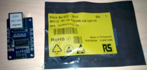
Pictured next to one of those ethernet to serial adapters that I ordered at least 2 months ago (which finally arrived today).. Yours looks like the 64pin baby.. I ordered the 100pin one.. I hope to mount mine on a UBW32 board.. I need to check pinouts first and work out if its worth doing. Mick Mick's uMite Stuff can be found >>> HERE (Kindly hosted by Dontronics) <<< |
||||
| palcal Guru Joined: 12/10/2011 Location: AustraliaPosts: 2039 |
I ordered mine from Microchip as Samples. They are sending 4 x 64pin and 2 x 100 pin. They were very quick, posted in 2 days from Thailand so should have them soon. Might as well get freebies if you can. Paul "It is better to be ignorant and ask a stupid question than to be plain Stupid and not ask at all" |
||||
| Grogster Admin Group Joined: 31/12/2012 Location: New ZealandPosts: 9975 |
Excellent thinking, Paul - I wish I had thought of that!  Smoke makes things work. When the smoke gets out, it stops! |
||||
| matherp Guru Joined: 11/12/2012 Location: United KingdomPosts: 11499 |
4.6b changes including the enhanced RTC and IR functions have been incorporated for the MX470s. Beta testers, please check your spam folders if you haven't received it. |
||||
| MicroBlocks Guru Joined: 12/05/2012 Location: ThailandPosts: 2209 |
I have a few observations for the 64 pin version. (I'll check the 100 pin later). In the pin description of the 64 pin chip there is no SPI out. The I2C on pins 31 and 32 can not be remapped to other pins. Why is the choice made to map the COM1 pins to those specific pins as it will prevent future use of the second I2C? In particular when more devices are used, like fram, flash, rtc, expanders, motor controllers, etc a second I2C will be very useful. Preventing that for future updates seems wrong to me. My suggestion would be to map COM1:RX to RPG7 (pin 5) and COM1:TX to RPG8 (pin 6). This will then also combine nicely with the COM1:Enable that is already mapped to RPG9 (pin 8) and it will help routing on the PCB as they are close together. Which pins are allocated for the 4th UART, or is that peripheral used by the IR? Which pins are allocated for the second SPI? This might be necessary to support an SD card. Otherwise it needs to be shared with the touchscreen or other usefull parts like WiFi/RF modules and other sensors. The VBUSON pin 11. Care should be taken because this pin will be unavailable once the decision is made to support USB. I am assuming that when USB is supported it will be in the device mode. The datasheet specifically mentions that this pin is 'reserved' and under control of the USB peripheral. In other modes like host and OTG this pin is used to provide power to the VBUS under software control. If you are using a complete port[0-15] for the databus to connect to the screen there is only one of those available on the 64 pin chip. That is port B. Port B however has the VBUSON on B5. When used for controlling the screen this will break once USB will be used. Even with the 100 pin chip, port B will have the same problem. However port D has all 16 bits available on the 100 pin. Does this mean that the only choice will be the 100 pin or would it be possible to use port B[8-15] and port D[0-7]. In that case it will work on both 64 and 100 pin device. Would using two 'half' ports be a lot slower? If you give me a list of which pins are used for the screens i could double check them for you to see if there are any conflicts. Microblocks. Build with logic. |
||||
| WhiteWizzard Guru Joined: 05/04/2013 Location: United KingdomPosts: 2991 |
Nice bit of 'detective' work there TZA 
IMHO these are all very good points raised which would be great to get feedback about from Peter and/or Geoff. I'm sure they have both considered the points raised but if not then this is certainly the time to try 'resolve' as many things as possible relating to pin-outs. Guess it is best to hold-off releasing any PCBs until the pinouts become confirmed.
WW |
||||
| matherp Guru Joined: 11/12/2012 Location: United KingdomPosts: 11499 |
I assume you are not on the beta program so the information you have is out-of-date. Latest version attached. There are no working PPS pins left on the 64-pin (other than port-B pins). Which functions should I sacrifice to free up the 2nd I2C? See list There is no 4th UART. IR on the 470 uses INT0 which is a non-PPS pin No way round this. It is perfectly possible to use non-contiguous pins in the Cfunctions. I've already run 16-bit parallel on the 44-pin which only has 10 pins on the C-port. It is just less optimal. If you want to use the 64-pin with a 16 bit parallel and USB just wire in another pin to replace RB5 (VBUSON) in the 16-bit port. Some of the mappings simply don't work. The original obvious allocation of F1 as console-RX on the 64-pin hit some sort of silicon error, then some of the logical alternatives didn't work on the 100-pin. I spent a huge amount of time finding a set that do work based on the testing I've done. We desperately need the beta program to get fully underway to really check things out. I'm not willing to make changes until there is a body of testers available. We could then allocate different hardware functions to different testers so that any change can be tested in parallel to check for unforeseen problems. 64-Pin Micromite Pin 1-PortE5:ANALOG_IN22 | DIGITAL_IN | DIGITAL_OUT | SPI2IN* Pin 2-PortE6 ANALOG_IN23 | DIGITAL_IN | DIGITAL_OUT Pin 3-PortE7 ANALOG_IN27 | DIGITAL_IN | DIGITAL_OUT Pin 4-PortG6 ANALOG_IN16 | DIGITAL_IN | DIGITAL_OUT | SPI2CLK* Pin 5-PortG7 ANALOG_IN17 | DIGITAL_IN | DIGITAL_OUT | SPI2OUT* Pin 6-PortG8 Console RX Pin 7-RESET/MCLR | 5V Pin 8-PortG9 ANALOG_IN19 | DIGITAL_IN | DIGITAL_OUT |SPIOUT Pin 9-GROUND Pin 10-POWER (+2.3 to +3.6V) Pin 11-PortB5 ANALOG_IN5 | DIGITAL_IN | DIGITAL_OUT Pin 12-PortB4 ANALOG_IN4 | DIGITAL_IN | DIGITAL_OUT Pin 13-PortB3 ANALOG_IN3 | DIGITAL_IN | DIGITAL_OUT Pin 14-PortB2 ANALOG_IN2 | DIGITAL_IN | DIGITAL_OUT Pin 15-PortB1 ANALOG_IN1 | DIGITAL_IN | DIGITAL_OUT | PGC Pin 16-PortB0 ANALOG_IN0 | DIGITAL_IN | DIGITAL_OUT | PGD Pin 17-PortB6 ANALOG_IN6 | DIGITAL_IN | DIGITAL_OUT Pin 18-PortB7 ANALOG_IN7 | DIGITAL_IN | DIGITAL_OUT Pin 19-ANALOG REFERENCE Pin 20-ANALOG GROUND Pin 21-PortB8 ANALOG_IN8 | DIGITAL_IN | DIGITAL_OUT Pin 22-PortB9 ANALOG_IN9 | DIGITAL_IN | DIGITAL_OUT Pin 23-PortB10 ANALOG_IN10 | DIGITAL_IN | DIGITAL_OUT | COUNT Pin 24-PortB11 ANALOG_IN11 | DIGITAL_IN | DIGITAL_OUT Pin 25-GROUND Pin 26-POWER (+2.3 to +3.6V) Pin 27-PortB12 ANALOG_IN12 | DIGITAL_IN | DIGITAL_OUT Pin 28-PortB13 ANALOG_IN13 | DIGITAL_IN | DIGITAL_OUT Pin 29-PortB14 ANALOG_IN14 | DIGITAL_IN | DIGITAL_OUT | Comm1 Enable Pin 30-PortB15 ANALOG_IN15 | DIGITAL_IN | DIGITAL_OUT Pin 31-PortF4 DIGITAL_IN | DIGITAL_OUT | 5V | Comm1 RX Pin 32-PortF5 DIGITAL_IN | DIGITAL_OUT | 5V | Comm1 TX Pin 33-PortF3 DIGITAL_IN | INTERRUPT | DIGITAL_OUT | 5V Pin 34-UNUSED | VBUS | 5V Pin 35-POWER (+2.3 to +3.6V) | USSB3V3 Pin 36-UNUSED | USBD- Pin 37-UNUSED | USBD+ Pin 38-POWER (+2.3 to +3.6V) Pin 39-PortC12 DIGITAL_IN | INTERRUPT | DIGITAL_OUT Pin 40-PortC15 DIGITAL_IN | INTERRUPT | DIGITAL_OUT Pin 41-GROUND Pin 42-PortD8 DIGITAL_IN | DIGITAL_OUT | 5V | PWM1B Pin 43-PortD9 DIGITAL_IN | DIGITAL_OUT | 5V | I2CSDA Pin 44-PortD10 DIGITAL_IN | DIGITAL_OUT | 5V | I2CSCL Pin 45-PortD11 DIGITAL_IN | DIGITAL_OUT | 5V | SPIIN Pin 46-PortD0 DIGITAL_IN | DIGITAL_OUT | 5V | COUNT | WAKEUP/IR Pin 47-PortC13 DIGITAL_IN | DIGITAL_OUT | PWM2B Pin 48-PortC14 DIGITAL_IN | DIGITAL_OUT | PWM1A Pin 49-PortD1 ANALOG_IN24 | DIGITAL_IN | DIGITAL_OUT | COUNT Pin 50-PortD2 ANALOG_IN25 | DIGITAL_IN | DIGITAL_OUT | SPICLK Pin 51-PortD3 ANALOG_IN26 | DIGITAL_IN | DIGITAL_OUT | COUNT Pin 52-PortD4 DIGITAL_IN | DIGITAL_OUT | 5V | COUNT Pin 53-PortD5 DIGITAL_IN | DIGITAL_OUT | 5V | PWM2A Pin 54-PortD6 DIGITAL_IN | INTERRUPT | DIGITAL_OUT | 5V Pin 55-PortD7 DIGITAL_IN | INTERRUPT | DIGITAL_OUT | 5V Pin 56-VCAP:47uF TANT CAPACITOR, 10|47uF Multilayer ceramic Pin 57-POWER (+2.3 to +3.6V) Pin 58-Console TX Pin 59-PortF1 DIGITAL_IN | DIGITAL_OUT | 5V Pin 60-PortE0 DIGITAL_IN | INTERRUPT | DIGITAL_OUT | 5V Pin 61-PortE1 DIGITAL_IN | INTERRUPT | DIGITAL_OUT | 5V | Comm2 RX Pin 62-PortE2 ANALOG_IN20 | DIGITAL_IN | DIGITAL_OUT | Comm2 TX Pin 63-PortE3 DIGITAL_IN | INTERRUPT | DIGITAL_OUT | 5V | PWM1C Pin 64-PortE4 ANALOG_IN21 | DIGITAL_IN | DIGITAL_OUT 100-Pin Micromite Pin 1-PortG15 DIGITAL_IN | DIGITAL_OUT | 5V Pin 2-POWER (+2.3 to +3.6V) Pin 3-PortE5 ANALOG_IN22 | DIGITAL_IN | DIGITAL_OUT | SPI2IN* Pin 4-PortE6 ANALOG_IN23 | DIGITAL_IN | DIGITAL_OUT Pin 5-PortE7 ANALOG_IN27 | DIGITAL_IN | DIGITAL_OUT Pin 6-PortC1 DIGITAL_IN | DIGITAL_OUT | 5V Pin 7-PortC2 DIGITAL_IN | DIGITAL_OUT | 5V Pin 8-PortC3 DIGITAL_IN | DIGITAL_OUT | 5V Pin 9-PortC4 DIGITAL_IN | DIGITAL_OUT | 5V Pin 10-PortG6 ANALOG_IN16 | DIGITAL_IN | DIGITAL_OUT | SPI2CLK* Pin 11-PortG7 ANALOG_IN17 | DIGITAL_IN | DIGITAL_OUT | SPI2OUT* Pin 12-PortG8 Console RX Pin 13-RESET/MCLR Pin 14-PortG9 ANALOG_IN19 | DIGITAL_IN | DIGITAL_OUT | SPIOUT Pin 15-GROUND Pin 16-POWER (+2.3 to +3.6V) Pin 17-PortA0 DIGITAL_IN | DIGITAL_OUT | 5V Pin 18-PortE8 DIGITAL_IN | DIGITAL_OUT | 5V Pin 19-PortE9 DIGITAL_IN | DIGITAL_OUT | 5V Pin 20-PortB5 ANALOG_IN5 | DIGITAL_IN | DIGITAL_OUT Pin 21-PortB4 ANALOG_IN4 | DIGITAL_IN | DIGITAL_OUT Pin 22-PortB3 ANALOG_IN3 | DIGITAL_IN | DIGITAL_OUT Pin 23-PortB2 ANALOG_IN2 | DIGITAL_IN | DIGITAL_OUT Pin 24-PortB1 ANALOG_IN1 | DIGITAL_IN | DIGITAL_OUT Pin 25-PortB0 ANALOG_IN0 | DIGITAL_IN | DIGITAL_OUT Pin 26-PortB6 ANALOG_IN6 | DIGITAL_IN | DIGITAL_OUT | PGC Pin 27-PortB7 ANALOG_IN7 | DIGITAL_IN | DIGITAL_OUT | PGD Pin 28-PortA9 DIGITAL_IN | DIGITAL_OUT Pin 29-PortA10 DIGITAL_IN | DIGITAL_OUT Pin 30-ANALOG REFERENCE Pin 31-ANALOG GROUND Pin 32-PortB8 ANALOG_IN8 | DIGITAL_IN | DIGITAL_OUT Pin 33-PortB9 ANALOG_IN9 | DIGITAL_IN | DIGITAL_OUT Pin 34-PortB10 ANALOG_IN10 | DIGITAL_IN | DIGITAL_OUT | COUNT Pin 35-PortA11 ANALOG_IN11 | DIGITAL_IN | DIGITAL_OUT Pin 36-GROUND Pin 37-POWER (+2.3 to +3.6V) Pin 38-PortA1 DIGITAL_IN | DIGITAL_OUT | 5V Pin 39-PortF13 DIGITAL_IN | DIGITAL_OUT | 5V Pin 40-PortF12 DIGITAL_IN | DIGITAL_OUT | 5V Pin 41-PortB12 ANALOG_IN12 | DIGITAL_IN | DIGITAL_OUT Pin 42-PortB13 ANALOG_IN13 | DIGITAL_IN | DIGITAL_OUT Pin 43-PortB14 ANALOG_IN14 | DIGITAL_IN | DIGITAL_OUT | Comm1 Enable Pin 44-PortB15 ANALOG_IN15 | DIGITAL_IN | DIGITAL_OUT Pin 45-GROUND Pin 46-POWER (+2.3 to +3.6V) Pin 47-PortD14 DIGITAL_IN | DIGITAL_OUT | 5V Pin 48-PortD15 DIGITAL_IN | DIGITAL_OUT | 5V Pin 49-PortF4 DIGITAL_IN | DIGITAL_OUT | 5V | Comm1 RX Pin 50-PortF5 DIGITAL_IN | DIGITAL_OUT | 5V | Comm1 TX Pin 51-PortF3 DIGITAL_IN | DIGITAL_OUT | 5V Pin 52-PortF2 DIGITAL_IN | DIGITAL_OUT | 5V Pin 53-PortF8 DIGITAL_IN | DIGITAL_OUT | 5V Pin 54-VBUS Pin 55-POWER (+2.3 to +3.6V) | VUSB3V3 Pin 56-D- Pin 57-D+ Pin 58-PortA2 DIGITAL_IN | DIGITAL_OUT | 5V Pin 59-PortA3 DIGITAL_IN | DIGITAL_OUT | 5V Pin 60-PortA4 DIGITAL_IN | DIGITAL_OUT | 5V Pin 61-PortA5 DIGITAL_IN | DIGITAL_OUT | 5V Pin 62-POWER (+2.3 to +3.6V) Pin 63-PortC12 DIGITAL_IN | INTERRUPT | DIGITAL_OUT Pin 64-PortC15 DIGITAL_IN | INTERRUPT | DIGITAL_OUT Pin 65-GROUND Pin 66-PortA14 DIGITAL_IN | DIGITAL_OUT | 5V | I2CSCL Pin 67-PortA15 DIGITAL_IN | DIGITAL_OUT | 5V | I2CSDA Pin 68-PortD8 DIGITAL_IN | DIGITAL_OUT | 5V | PWM1B Pin 69-PortD9 DIGITAL_IN | DIGITAL_OUT | 5V Pin 70-PortD10 DIGITAL_IN | DIGITAL_OUT | 5V | SPICLK Pin 71-PortD11 DIGITAL_IN | DIGITAL_OUT | 5V | SPIIN Pin 72-PortD0 DIGITAL_IN | DIGITAL_OUT | 5V | COUNT | WAKEUP/IR Pin 73-PortC13 DIGITAL_IN | DIGITAL_OUT | PWM2B Pin 74-PortC14 DIGITAL_IN | DIGITAL_OUT | PWM1A Pin 75-GROUND Pin 76-PortD1 ANALOG_IN24 | DIGITAL_IN | DIGITAL_OUT | COUNT Pin 77-PortD2 ANALOG_IN25 | DIGITAL_IN | DIGITAL_OUT Pin 78-PortD3 ANALOG_IN26 | DIGITAL_IN | DIGITAL_OUT | COUNT +- Pin 79-PortD12 DIGITAL_IN | DIGITAL_OUT | 5V Pin 80-PortD13 DIGITAL_IN | DIGITAL_OUT | 5V Pin 81-PortD4 DIGITAL_IN | DIGITAL_OUT | 5V | COUNT Pin 82-PortD5 DIGITAL_IN | DIGITAL_OUT | 5V | PWM2A Pin 83-PortD6 DIGITAL_IN | INTERRUPT | DIGITAL_OUT | 5V Pin 84-PortD7 DIGITAL_IN | INTERRUPT | DIGITAL_OUT | 5V Pin 85-VCAP:47uF TANT CAPACITOR, 10|47uF Multilayer ceramic Pin 86-POWER (+2.3 to +3.6V) Pin 87-Console TX Pin 88-DIGITAL_IN | DIGITAL_OUT | 5V Pin 89-PortG1 DIGITAL_IN | DIGITAL_OUT | 5V Pin 90-PortG0 DIGITAL_IN | DIGITAL_OUT | 5V Pin 91-PortA6 DIGITAL_IN | DIGITAL_OUT | 5V Pin 92-PortA7 DIGITAL_IN | DIGITAL_OUT | INTERRUPT | 5V Pin 93-PortE0 DIGITAL_IN | DIGITAL_OUT | INTERRUPT | 5V Pin 94-PortE1 DIGITAL_IN | DIGITAL_OUT | 5V | Comm2 RX Pin 95-PortG14 DIGITAL_IN | DIGITAL_OUT | 5V Pin 96-PortG12 DIGITAL_IN | DIGITAL_OUT | 5V Pin 97-PortG13 DIGITAL_IN | DIGITAL_OUT | 5V Pin 98-PortE2 ANALOG_IN20 | DIGITAL_IN | DIGITAL_OUT | Comm2 TX Pin 99-PortE3 DIGITAL_IN | INTERRUPT | DIGITAL_OUT | 5V | PWM1C Pin 100-PortE4 ANALOG_IN21 | DIGITAL_IN | DIGITAL_OUT |
||||
| MicroBlocks Guru Joined: 12/05/2012 Location: ThailandPosts: 2209 |
Unfortunately i can not beta test right now. Stuff is on its way and then i can join. I expect chips to arrive early next week. Is there a repository where the source code can be worked upon. Github for example works great for this and it allows projects to be private so that not everyone can access it. I have a paid account that can hold private projects if nothing exists at the moment to get things rolling. It will also allow changes to be committed easily and merge with the master once it is tested and approved. The dictator model is probably best. :) Which software stack are you using? I can setup a similar environment to prevent differences in compiler versions and settings. Microblocks. Build with logic. |
||||
| matherp Guru Joined: 11/12/2012 Location: United KingdomPosts: 11499 |
No. I don't think any sort of "group" development is appropriate, (plus I hate and despise Github ).
I obtained permission from Geoff to undertake the development and he, subject to auditing my work, has indicated it will become part of his formal "Micromite" release once the beta is successfully completed. At this point I will stop developing the code as part of the handover. You are of course perfectly free to download the MX170 code from Geoff's site and develop it yourself subject to meeting the licence conditions. |
||||
| robert.rozee Guru Joined: 31/12/2012 Location: New ZealandPosts: 2528 |
expanding on the words of matherp above - there have been long discussions over the years on this forum regarding the availability and licensing of the micromite source code. Geoff Graham has always been extremely accommodating in making the code available on a one-to-one basis to anyone who would like to look at it, subject to a few copyright provisos to protect Geoff's own interests. yet every now and then one of a very small group of people 'needle' the author a little over access to the mmbasic source code. never anything major, just a little reminder 'jab'. as those who have been around here for a while know, a public repository is inconsistent with the licensing of Geoff's code. i am upset as the 'needling' is undignified, certainly unhelpful, and reflects badly on the character of those who choose to undertake it. robert rozee |
||||
| MicroBlocks Guru Joined: 12/05/2012 Location: ThailandPosts: 2209 |
That was uncalled for, now i am upset. When someone is beta testing some software how else would you help each other. By just loading a hex file? That will give you only 'Doesn't work'. Not the why. What i suggested is a CLOSED repository where some experimenting can take place without disturbing someone elses experiments. In a repository you just make a new branch and have your own local copy to work with. The dictator model allows then for ONE person to commit those changes to a master. The dictator keeps full control, as it should be. I understand Geoffs reasoning very well, as with open source it tends to go off in all directions and focus is lost while all the blame squarly goes back to the initiator/creator. Geoff already freely sends the sourcecode to any one who asks. No 'needling' necessary. Microblocks. Build with logic. |
||||
| The Back Shed's forum code is written, and hosted, in Australia. | © JAQ Software 2026 |
