
|
|
Forum Index : Microcontroller and PC projects : MicroMite+ Explore64 PCB 1C...
| Author | Message | ||||
| MicroBlocks Guru Joined: 12/05/2012 Location: ThailandPosts: 2209 |
The most safe solution would be to have 3 pins and a 2 pin jumper. [code] 5v from USB - - 5v from external | | 0 0 0 | --- vdd to the voltage regulator [/code] You then connect the 5v from the usb to the left pin, 5Vin to the right pin. The middle pin will then have either the USB or the 5Vin, impossible to have both. Very 'idiot' proof. A switch would then also be good. Microblocks. Build with logic. |
||||
Grogster Admin Group Joined: 31/12/2012 Location: New ZealandPosts: 9975 |
@ Geoff - Like this: 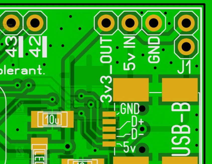
J1 just connects the USB 5v through to the regulator input - no diodes, no MOSFET, no PTC. If you want to power the module from USB, install J1. If you want to power the module externally, remove J1. With J1 removed, USB console will still work, provided you have external power. When the time comes for USB keyboards(if/when), then power externally AND install J1, but that would be the only time you would have that configuration. Smoke makes things work. When the smoke gets out, it stops! |
||||
| robert.rozee Guru Joined: 31/12/2012 Location: New ZealandPosts: 2527 |
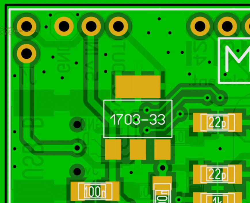
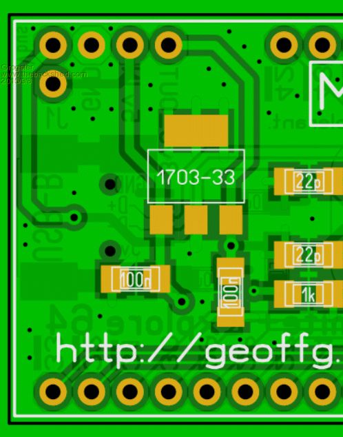
looks like a simpler solution 
btw, i did accidentally connect up an MX170 with power reversed the other day, and it still works (ie, survived). one observation: if you push the trace between the "3v3_OUT" pin and the output of the regulator to the opposite side of the board, you can eliminate the 3 small 'jumper' tracks that originate under the regulator. this saves 6 vias (which in olden times would be a cost saving), and avoids vias in a location (under the regulator) which in some devices can be metal. cheers, rob :-) |
||||
| Grogster Admin Group Joined: 31/12/2012 Location: New ZealandPosts: 9975 |
Hey Rob. 
I think I see what you mean, but in this case, the reg is plastic-backed, so no problem there, and you can have as many vias as you like for the same price. 
I did not know that you used to get charged by via-count in the old days - interesting information. EDIT: I see the merit in your suggestion - I will change the layout. EDIT: Like this? 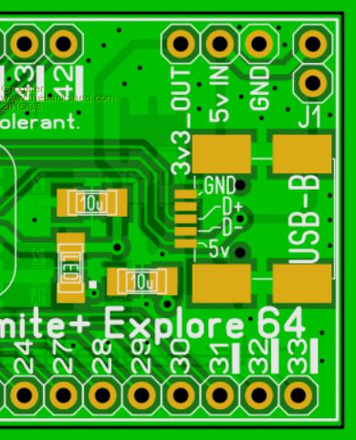
Smoke makes things work. When the smoke gets out, it stops! |
||||
| Geoffg Guru Joined: 06/06/2011 Location: AustraliaPosts: 3362 |
Yes Grogs, that looks great. If you want to fine tune the layout you could swap Vbus and +5V on the two pin jumper and then push the pins slightly closer to the ground pin so that the spacing between the Vbus jumper pin and the ground pin is 0.1". That way someone could solder the single Vbus jumper pin on the underside of the board and have a row of four breadboard compatible pins with Vbus on one of them. It might not get used much but it would enable someone to wire their own circuit connecting Vbus to +5V (perhaps using Rob's circuit). Yes, they are tough little chips. When I was developing the Maximite I accidentally ran an MX795 on 5V for a few hours and it survived. Geoff Geoff Graham - http://geoffg.net |
||||
| Grogster Admin Group Joined: 31/12/2012 Location: New ZealandPosts: 9975 |
Like this? 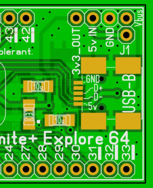
Smoke makes things work. When the smoke gets out, it stops! |
||||
| Geoffg Guru Joined: 06/06/2011 Location: AustraliaPosts: 3362 |
Excellent Grogs. I cannot think of anything else. Geoff Graham - http://geoffg.net |
||||
| robert.rozee Guru Joined: 31/12/2012 Location: New ZealandPosts: 2527 |
looks great! if you wanted to, you could push the 10uF capacitor (attached to the LED) slightly left, then bring out a trace from the 'sense' pin on the USB connector. this could run to a test point, or (via a solderable link or directly) to pin 42. just in case in the future the select pin is needed. and even if not used for select, this USB pin could act as a spare user input via a 5-way USB cable - i've seen the sense pin used like this for remote shutter release on some fuji digital cameras. cheers, rob :-) |
||||
| Grogster Admin Group Joined: 31/12/2012 Location: New ZealandPosts: 9975 |
Like this? 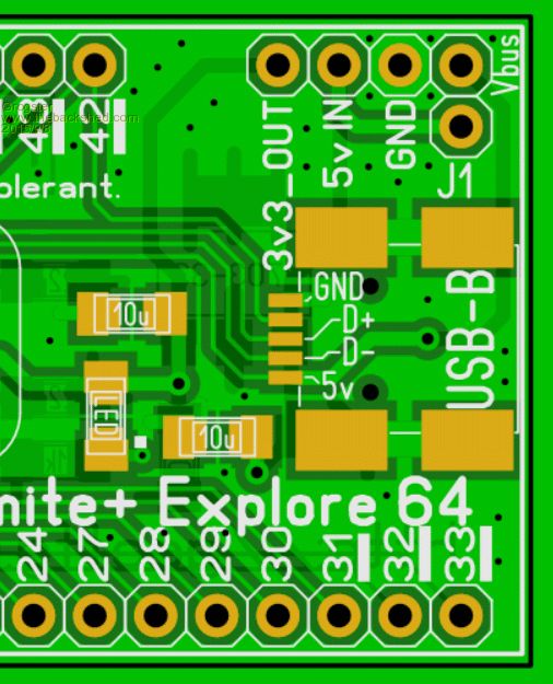
Smoke makes things work. When the smoke gets out, it stops! |
||||
| robert.rozee Guru Joined: 31/12/2012 Location: New ZealandPosts: 2527 |
yep, that is what i had in mind. you just need to confer with geoff, as hard-wiring 'select' to pin 42 will (if a USB OTG cable is plugged in) short pin 42 to ground. the MM+ manual will need to be amended to reflect this. i have no idea what the current functions on pin 42 are. addendum: pin 42 is PWM 1B. addendum#2: pin 30 could be a good choice, and a track could be got through. addendum#3: pin 33 looks like an even better candidate, as it is an input only, non-analog, and 5v tolerant. cheers, rob :-) |
||||
| Grogster Admin Group Joined: 31/12/2012 Location: New ZealandPosts: 9975 |
Hokey, pokey. I will wait for Geoff to reply as to his needs. Smoke makes things work. When the smoke gets out, it stops! |
||||
| MicroBlocks Guru Joined: 12/05/2012 Location: ThailandPosts: 2209 |
Pin 33 seems to be made for that function. It is the least 'versatile' pin. Microblocks. Build with logic. |
||||
| Grogster Admin Group Joined: 31/12/2012 Location: New ZealandPosts: 9975 |
Agreed. I will ask Geoff for his opinion. Smoke makes things work. When the smoke gets out, it stops! |
||||
| MMAndy Regular Member Joined: 16/07/2015 Location: United StatesPosts: 91 |
Grogs ... Any idea on the projected estimated date in which a user could obtain the version 1C board? A projected month will suffice |
||||
| Grogster Admin Group Joined: 31/12/2012 Location: New ZealandPosts: 9975 |
Hey there.
I have Geoff's approval to use pin33 for the SENSE input(with solder-blob pads) for the USB, which he provided about a week ago. I need to update the layout pattern, then post the images here for final forum approval(well, as much as you can with design-by-committee(forum!)), but I think we have a board that covers just about all aspects that other members have have talked about. I will try to make the mod tonight, and upload images, and then yes - about a month for the new boards to arrive. Usually about 2-3 weeks, but I always allow a little more for good luck. Smoke makes things work. When the smoke gets out, it stops! |
||||
| Zonker Guru Joined: 18/08/2012 Location: United StatesPosts: 772 |
Sweet Grogs..!! Awesome PCB..  |
||||
| Grogster Admin Group Joined: 31/12/2012 Location: New ZealandPosts: 9975 |
UPDATE Here we go then: TOP: 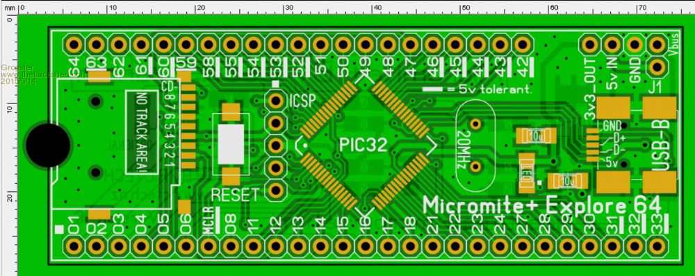
BOTTOM: 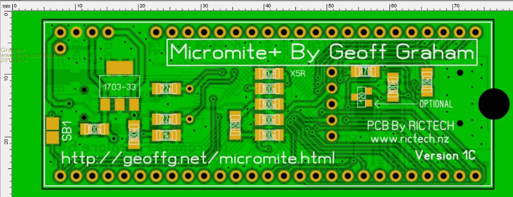
This should cover all the bases now - with any luck. 
If/when needed, you put a solder blob on the "SB1" pads, and this will connect the USB-B Sense pin, to pin33 on the module. You can leave SB1 open to use pin33 as a normal input-only pin. I am not planning on adding any new features to this board now - it is very crowded on there now as it is, but if anyone sees any electronic errors with the layout, please do post your observations here, so I can fix them before ordering the boards. Assuming there are no errors(or none that are noticed!), I will order a batch of boards by the end of the week. Smoke makes things work. When the smoke gets out, it stops! |
||||
| robert.rozee Guru Joined: 31/12/2012 Location: New ZealandPosts: 2527 |
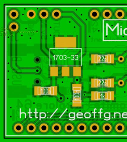
the part number for the supervisory chip seems to have changed from "130" to "120", is this intended? and i do believe that the tracking around the 4 components in that area could be simplified a little - if the 10k resistor were moved to the other side of the long trace that runs to pin 14, then the RH end of the 10k could run directly to the supervisor (instead of to the RH end of the 470r) and a couple of vias plus short link under the SD socket would be eliminated. addendum: there may also be a benefit from a little more copper running to the ground pin on the USB connector. it looks a little light, though is hard to make out for sure. cheers, rob :-) |
||||
| Grogster Admin Group Joined: 31/12/2012 Location: New ZealandPosts: 9975 |
OK on USB GDN pin - easy. Trying to visualize what you mean by the rest of your post - can you provide a bit more detail? EDIT: Ahhhhhhhh - I think I see what you mean. Will make some changes..... Smoke makes things work. When the smoke gets out, it stops! |
||||
| Chris Roper Senior Member Joined: 19/05/2015 Location: South AfricaPosts: 280 |
Grogs, One last suggestion if I may, and it won't take up any extra board space. If you slightly stagger the alternate PINS of the ICSP footprint people will be able to Press Fit a header in there long enough to Flash the Device, without having to permanently mount one. Here is an example from another Board to show what I mean. 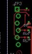
Cheers Chris http://caroper.blogspot.com/ |
||||
| The Back Shed's forum code is written, and hosted, in Australia. | © JAQ Software 2026 |
