
|
|
Forum Index : Microcontroller and PC projects : MicroMite controlled 4-CH stereo...
| Author | Message | ||||
Grogster Admin Group Joined: 31/12/2012 Location: New ZealandPosts: 9973 |
UPDATE PCB's have arrived. Let the construction begin. 
We'll see how things go, but I probably will need to pester some of you for some I2C help, if the processor chip does not want to co-operate, or I am misunderstand the PDF for it. I will upload the PDF here, if I have any issues. I am hopeful that it will just work as planned, but I2C is an unforgiving protocol - only one way to get it right, many ways to get it wrong(commands, that is), and the slave device won't help you out of your mistakes. 
I will update this thread again, once I have assembled the PCB's, which I hope to do tonight. Smoke makes things work. When the smoke gets out, it stops! |
||||
| Grogster Admin Group Joined: 31/12/2012 Location: New ZealandPosts: 9973 |
UPDATE Pre-amp board complete! 
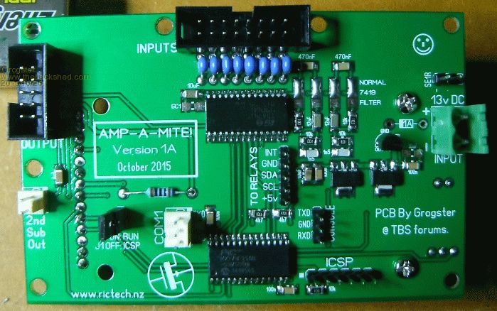
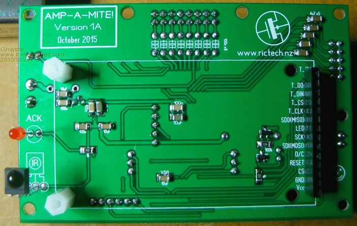
I have not tempted fate by firing it up tonight - it 2:45AM now. I will fire up tomorrow and see what happens. I still have to assemble the relay board and the input sockets board, but they are smaller and have less component density. EDIT: Oppps - forgot the diode on the PSU input - but I have fitted it now. Smoke makes things work. When the smoke gets out, it stops! |
||||
| WhiteWizzard Guru Joined: 05/04/2013 Location: United KingdomPosts: 2978 |
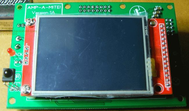
Looks great G. (Are you winding me up with that photo of a ILI9341 TFT module )
|
||||
| viscomjim Guru Joined: 08/01/2014 Location: United StatesPosts: 925 |
HELL YEAH!! Nice job there Grogster. That is bad ass!!!! |
||||
| Grogster Admin Group Joined: 31/12/2012 Location: New ZealandPosts: 9973 |
@ WW - LOL!!!!!  No, this is the one I will 'Unplug' from this pre-amp board, to test that idea tomorrow on a MM+. No, this is the one I will 'Unplug' from this pre-amp board, to test that idea tomorrow on a MM+.
@ viscomjim - I hope it sounds as bad-ass when I get it going! 
Time to rest my brain. I will do another update tomorrow. Smoke makes things work. When the smoke gets out, it stops! |
||||
| Grogster Admin Group Joined: 31/12/2012 Location: New ZealandPosts: 9973 |
UPDATE Relay and input RCA boards complete. 
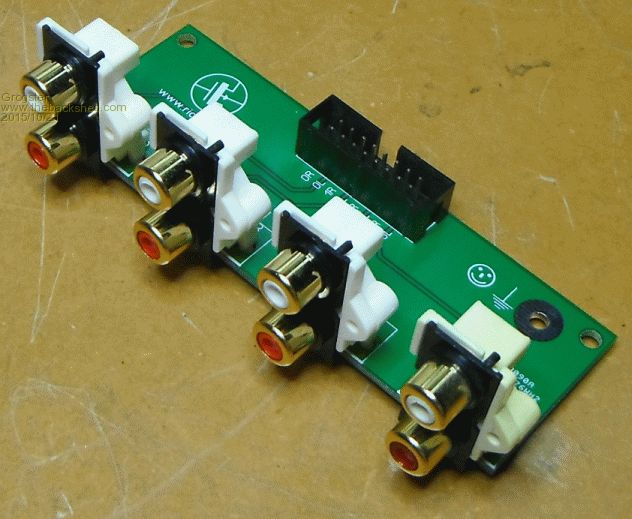
Let the experimentation begin! Smoke makes things work. When the smoke gets out, it stops! |
||||
| WhiteWizzard Guru Joined: 05/04/2013 Location: United KingdomPosts: 2978 |
BANG!!
I can almost here the sound already. These are well neat G. WW |
||||
| Grogster Admin Group Joined: 31/12/2012 Location: New ZealandPosts: 9973 |
BANG?! Owwwww, you meanie, WW....
Have not forgotten your LCD test - that is actually next, before I play with these modules. Smoke makes things work. When the smoke gets out, it stops! |
||||
| WhiteWizzard Guru Joined: 05/04/2013 Location: United KingdomPosts: 2978 |
Thanks for any testing. I have rewired everything and still the same LOAD Image issue. Anyway - keep posting with your progress with these nice looking PCB Modules. Do you think you will get any sound out of them tonight? |
||||
| Grogster Admin Group Joined: 31/12/2012 Location: New ZealandPosts: 9973 |
No. It's 12:38AM already, and last thing I plan to play with is the LCD on the MM+, so I will post back on that thread with results. I need a clear run on the stereo PCB's - best not to start on them at midnight. If something goes wrong, I could be up all night. Not good for tomorrows work! Smoke makes things work. When the smoke gets out, it stops! |
||||
| Grogster Admin Group Joined: 31/12/2012 Location: New ZealandPosts: 9973 |
UPDATE I have programmed MMBASIC in and tested the LCD screen on the main pre-amp board, and programmed MMBASIC into the relay control board and run some test code. All of this is working fine. 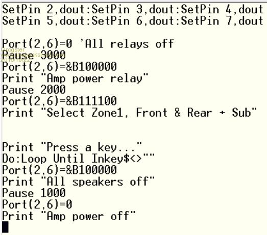
This just simulates the power-up and power-down sequence used to prevent start-up/shut-down speaker thumps. As yet, not tested any I2C on the 7914(perhaps I am scared? ), but all voltages appear correct and nothing is doing anything odd during my initial firmware programming, configuration and testing.
I2C tinkering will begin tomorrow. I am going to build this unit into a wooden sub box, which I will custom-build to fit 2x 8" 90W subwoofer speakers. This allows me to build the sub, and enclose the amp all at the same time. I will get the front and rear panels laser-cut and powder-coated to suit. Smoke makes things work. When the smoke gets out, it stops! |
||||
| Grogster Admin Group Joined: 31/12/2012 Location: New ZealandPosts: 9973 |
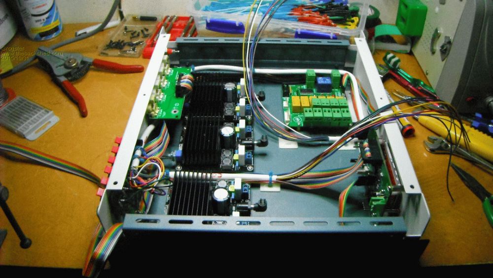
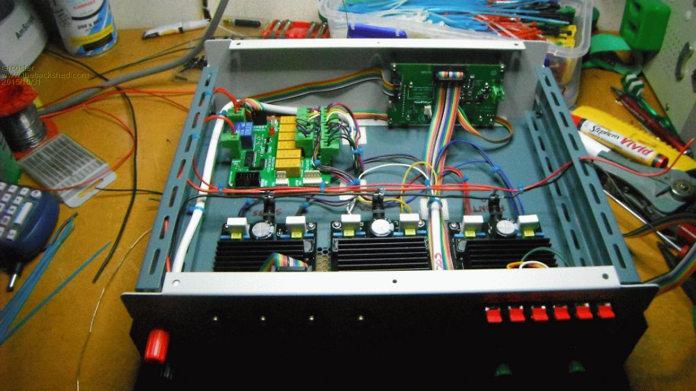
UPDATE Tonight I got a chance to attack the case and get things mounted. 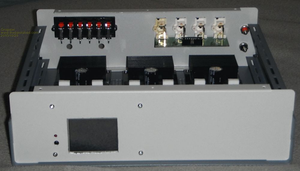
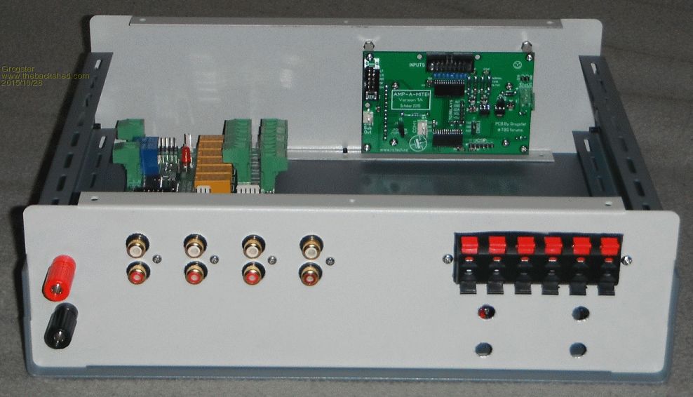
No room for PSU!
The red and black banana sockets on the back will connect to an external 36v(wound back to 32v) PSU. This PSU can pump out 11-amps, so that should be sufficent!
The three boards on this thread are easy enough to spot, but the new cast members are the 6-way speaker connector, and 3x amplifier boards. These boards are 100W stereo power amp modules in class-D arrangement. At 32v, these amps can deliver about 92W RMS @ 10% THD. That is essentially the standard measurement figure, but 10% THD is not a good thing, really. Looking further at the datasheet, the amp is capable of about 70W RMS @ 0.1% THD, which is a much better distortion figure. Hell, for fifteen bucks, it's not a bad amp!!! 
One amp for front, one amp for rear, one amp for subs. EDIT: Oh, forgot to mention: Four holes in back panel are for the subs, but I ran out of banana sockets. The 6-way speaker connector deals with front, zone 2 and rear speaker sets. Smoke makes things work. When the smoke gets out, it stops! |
||||
| MicroBlocks Guru Joined: 12/05/2012 Location: ThailandPosts: 2209 |
When you define the pins as output do you not have the risk that one of them will be a '1'? I think the safest way is to have pull down resistors as the uMite startup with all pins in high impedance state. Then after that set the pins to 0 and then finally to an output. Well, that is the theory. :) Microblocks. Build with logic. |
||||
| Grogster Admin Group Joined: 31/12/2012 Location: New ZealandPosts: 9973 |
To what specifically, are you referring? The relay board outputs? Smoke makes things work. When the smoke gets out, it stops! |
||||
| MicroBlocks Guru Joined: 12/05/2012 Location: ThailandPosts: 2209 |
The first 3 lines of the code in your post where you define the pins and set them. Microblocks. Build with logic. |
||||
| Grogster Admin Group Joined: 31/12/2012 Location: New ZealandPosts: 9973 |
OK. These pins connect directly to the ULN2003A darlington driver IC. Each of these pins drives the base of a NPN darlington pair, with a 2k7 base resistor, so I think it SHOULD be pretty safe for all forseeable situations.
Each of the darlington pairs consist of: 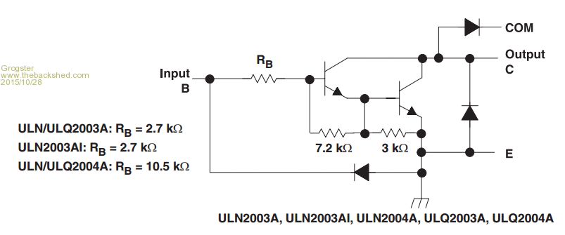
Smoke makes things work. When the smoke gets out, it stops! |
||||
| MicroBlocks Guru Joined: 12/05/2012 Location: ThailandPosts: 2209 |
Maybe i am too careful but it could be possible one of those pins is a '1' when you don't want it at the moment you define them as outputs. It 'should' be a '0' but there is no guarantee. The pic itself at startup (and after reset) puts all pins in high impedance, after that it is the programmers responsibility. It is not life threatening so not have to worry too much. :) I am not good at darlington stuff so i am not sure that when the input is floating how it will respond. Microblocks. Build with logic. |
||||
| Grogster Admin Group Joined: 31/12/2012 Location: New ZealandPosts: 9973 |
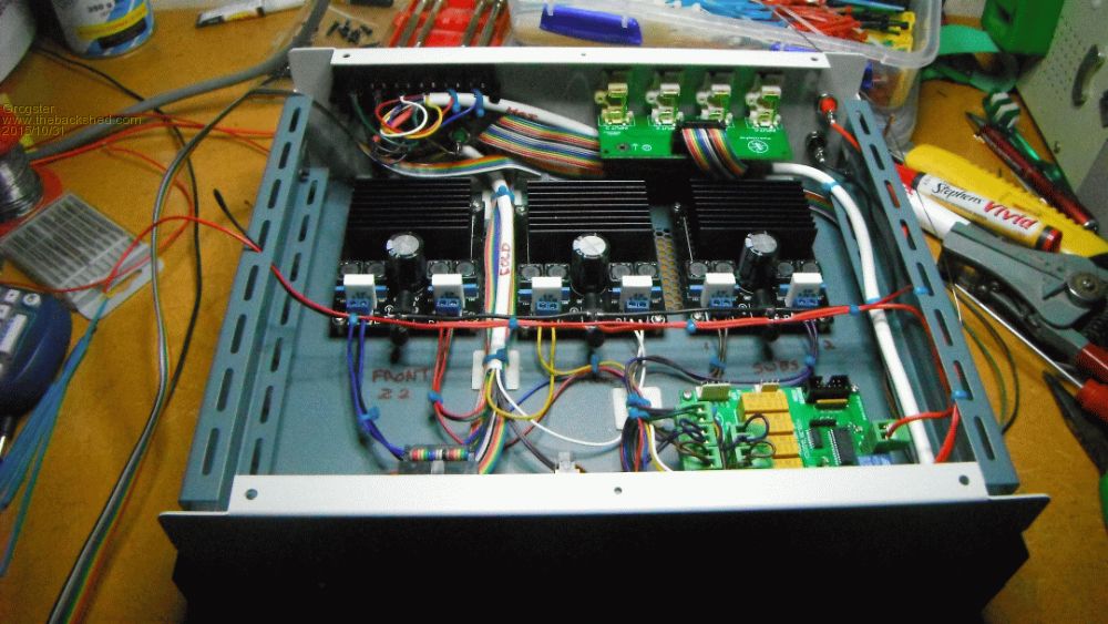
UPDATE Assembly continues - there are more wires then I thought there would be.
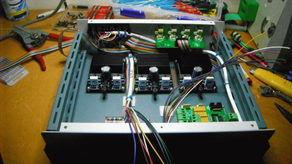
The 8-core cable labelled 'HOT' is the positive side of the speaker output, and the 8-core labelled 'COLD' is the negative side of the speaker output. As all these amps do NOT have a common ground, each speaker output needs it's own unique and separate negative connection - that tends to make for quite a lot of speaker wires.
However, you can see how the 'COLD' cable connects all the negatives to the respective speaker outputs, and the 'HOT' cable comes from the de-thump/routing board which will switch speakers on and off as desired etc. There is a third 8-core cable to go in yet, connecting the amp hot outputs to the relay board. Also still have to fit buck-regulator on main PSU rail to supply 12v to the MM-based electronics and relay board, and also still have to install and route the main 32v bus. I will post more photos when the wiring is complete. Almost ready to actually do some testing!!!!
Smoke makes things work. When the smoke gets out, it stops! |
||||
| Grogster Admin Group Joined: 31/12/2012 Location: New ZealandPosts: 9973 |
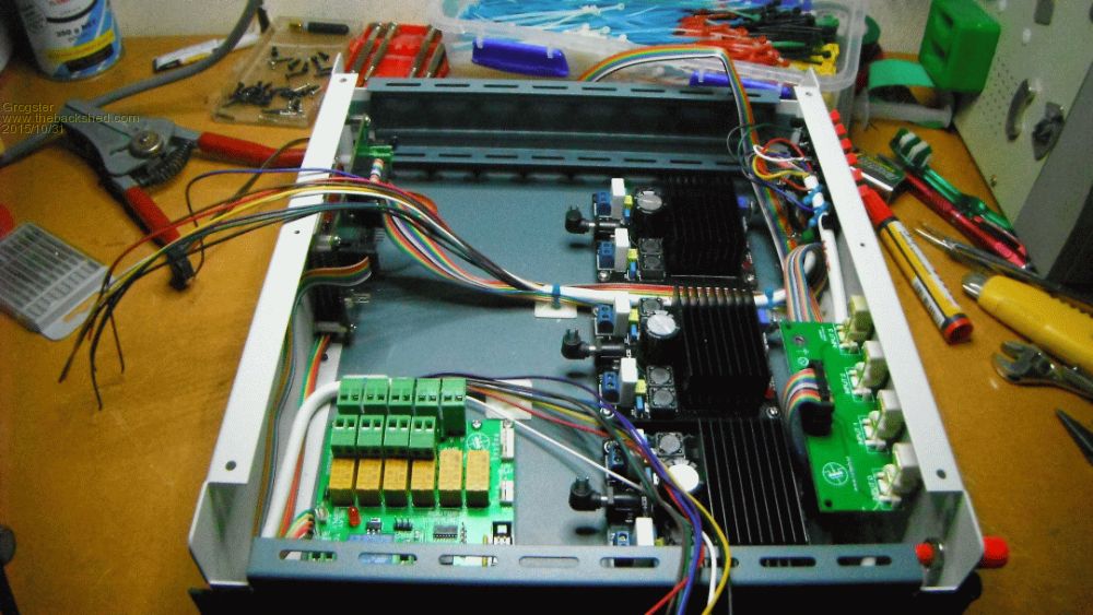
UPDATE ...almost finished! 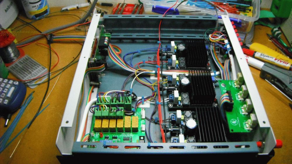

The red and black hanging off the left side of the box is the 32v input, which will connect to the buck converter, the 12v output of which, will power the circuits. With any luck, I will be able to fire it up tomorrow and do some preliminary testing.
For now, it is 2:20AM, so time to call it quits!!!  Smoke makes things work. When the smoke gets out, it stops! |
||||
| Chris Roper Senior Member Joined: 19/05/2015 Location: South AfricaPosts: 280 |
It's only 2 and a half hours till the match, you may as well work on then watch :) http://caroper.blogspot.com/ |
||||
| The Back Shed's forum code is written, and hosted, in Australia. | © JAQ Software 2026 |
