
|
|
Forum Index : Microcontroller and PC projects : Triggerd PWM..
| Author | Message | ||||
| Warpspeed Guru Joined: 09/08/2007 Location: AustraliaPosts: 4406 |
Here are some voltage waveforms for a three phase half controlled bridge. With very late triggering (and a low output) the SCRs operate independently pretty much as you would expect. As you advance the firing angle to be earlier, a curious double hump appears beyond sixty degrees and the whole nature of the waveform changes. The waveforms below are for a resistive load. Its a very difficult thing to visualise or to explain, you really need to watch it happen on an oscilloscope. There are many waveform variations possible, a bridge can be half controlled or fully controlled, and the load may be resistive or inductive or a mix of both. There may also be a flyback diode fitted, and sometimes not. And the waveforms can totally change their shape at some point in the control range. Its been a very long time since I played around with any of this, so would be starting out from scratch trying to remember the precise details. An engineering textbook or internet search might be your best bet. 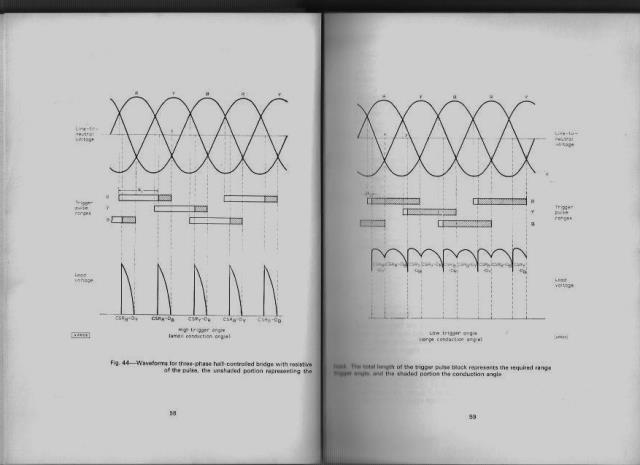 Cheers, ĀTony. |
||||
Chopperp Guru Joined: 03/01/2018 Location: AustraliaPosts: 1123 |
Thanks fof that Tony. Time for some sleep  Brian ChopperP |
||||
| Warpspeed Guru Joined: 09/08/2007 Location: AustraliaPosts: 4406 |
Yes its getting a bit late. Cheers, ĀTony. |
||||
| Chopperp Guru Joined: 03/01/2018 Location: AustraliaPosts: 1123 |
Update: My Mains triggered Phase Control progress. From matherp's Csub Here , I've had some success in getting single phase PWM working. The "oneshot" function gives the delay & width & with a bit of math in the program I was able to get the main pulse occurring ending just prior to the next trigger & working backward from there. I also gated in 15000Hz pulses for high freq transformer triggering of the SCR. The first main problem I came across was that the two pulse trains continued when the program was stopped. This is normal operation but not good for this situation. After a fair bit of head scratching & experimenting, I ended up having a signal O/P generated by the program, AC coupling it to a rectifier which supplied volts to a transistor which kept the gating circuit energised. If the program stopps, the gating pulses also stop. The other thing was to set the limits for the delay so false triggering would not occur & the pulses occurred within the correct time frame. Also the delay & width variables have to be integers. The gated output is fed to a driver circuit which feeds a small transformer with it's secondary connected between the gate & cathode of the SCR. The SCR was connected in series to the output of a 4A (nom) battery charger with about a 30 ohm element for a dummy load. This load was a bit light on for the SCR used. It's holding current was too low at the low voltage ends of the input. I've only implemented manual control over the output width at this stage. Both o/p voltage & current feedback (among other things) are still to be implemented. The ultimate goal is for a 70V, ~20A battery charger & a high current power supply. (Yes I know SMPS's is probably the better way to go but this is fun) Code, some Photos & rough circuit shown following. Thanks to all especially to matherp for the lightning fast Csub. 2018-06-19_212432_PWM_01_CCT.pdf Test code so far inc the Csub 'PWM_Phase_Test_matherp_03.bas option autorun on pwm 2, 15000, 50 'PIN 26. HF trigger pulses for the SCR, gated by PIN 14 setpin 15, CIN 'Trigger input setpin 7, ain 'Sample (Control) volts in. 0-3V3 oneshot 0,0,0 'reset oneshot delay% = 9000 'set initial value for Oneshot width% = 500 'set initial value for Oneshot pause 2500 oneshot 25, delay%, width% 'Pin, delay & width pause 2500 setpin 16, inth, trigger 'PIN 16 connected to PIN 15 to capture trigger setpin 24, dout 'Check prog is running pin(17) = 0 'set value do delay% = max(850, min(9500, (pin(7) * 3000))) 'delay limited from ~ 0.5mS to 9.5mS width% = 9850 - delay% 'start = max delay - current delay pause 5 'simulating doing other stuff loop sub trigger oneshot 25, delay%, width% 'set O/P on PIN 17 watchdog 200 'reset program if input fails pin(24) = not pin(24) 'toggles PIN 24. Used to check prog running end sub ' subroutine oneshot ' outputs a positive going pulse after a pre-determined period after a trigger pulse is received ' will continute to respond to each trigger pulse received until the output is turned off. ' The trigger pulse must be applied to pin 15 of a 28-pin Micromite which must be previously set up as a counting input ' ' This function takes as parameters the following ' ' pin number of the pin to output the pulse ' pause after trigger before the pulse in microseconds (maximum is 524288/CPU speed = 13.1mSec @ 40MHz ' duration of the pulse in microseconds (maximum is 524288/CPU speed = 13.1mSec @ 40MHz ' ' Use pin number = 0 to turn off the output ' ' WARNING - the program has no error checking. Pulse durations greater than specified above will be rounded down modulus 524288/CPU speed ' CSub oneshot 00000030 'T1Int 3C039D00 8C62008C 8C450014 3C04BF80 AC850620 8C440008 8C420004 AC820000 8C63008C 8C62000C 2444FFFF 14400008 AC64000C 24030010 3C02BF88 AC431064 3C02BF88 AC401068 3C02BF80 AC400600 03E00008 00000000 'E2Int 3C029D00 8C43008C 24040001 AC64000C 8C42008C 8C430010 3C02BF80 AC430620 34038010 3C02BF80 AC430600 24020010 3C03BF88 AC621064 3C03BF88 AC621068 03E00008 00000000 'getFPC 27BDFFF8 AFBF0004 00852023 03E42021 ACC40000 8FBF0004 03E00008 27BD0008 'main 27BDFFC8 AFBF0034 AFB50030 AFB4002C AFB30028 AFB20024 AFB10020 AFB0001C 00808021 00A08821 00C09021 00002021 3C059D00 24A50104 27A60010 0411FFE8 00000000 8E530000 3C029D00 8C420000 8C520000 8E020000 8E030004 00431025 1440000E 8E340000 24030010 3C02BF88 AC431064 3C02BF88 AC401068 3C02BF80 AC400600 3C029D00 8C4300CC AC600000 8C4200AC 1000004B AC400000 3C029D00 8C4200CC 8C420000 1440002A 3C03BF80 24030010 3C02BF88 AC431064 3C02BF88 AC401068 3C119D00 8E220010 8E040000 24050008 0040F809 00003021 8E35008C 8E220024 8E040000 0040F809 24050007 AEA20008 8E35008C 8E220028 0040F809 8E040000 24030001 00431004 AEA20004 8E22001C 8E040000 0040F809 24050005 8FA40010 8E2200CC 3C039D00 24630058 00641821 AC430000 8FA40010 8E2200AC 3C039D00 24630000 00641821 10000004 AC430000 8C620600 1440FFFE 00000000 3C029D00 8C43008C 24040001 AC64000C 001290C2 3C03000F 24634240 0243001A 006001F4 00009012 8C43008C 7254A002 AC740010 8C42008C 72539002 AC520014 2403001C 3C02BF88 AC4310A4 24030004 3C02BF88 AC4310A8 24030010 3C02BF88 AC431034 8FBF0034 8FB50030 8FB4002C 8FB30028 8FB20024 8FB10020 8FB0001C 03E00008 27BD0038 End CSub 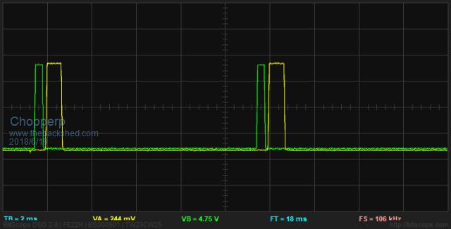 Oneshot pulse (green) occurring just before the next trigger pulse (Yellow). Min O/P 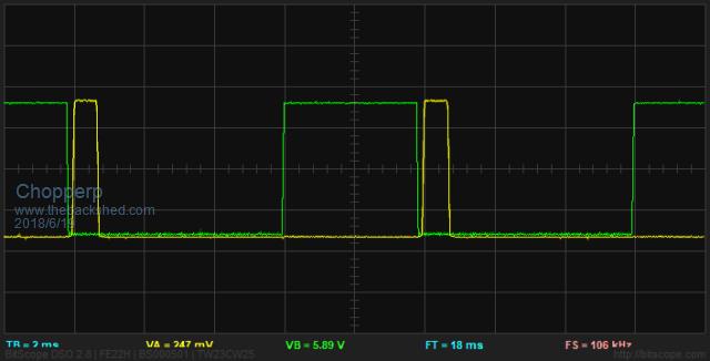 Oneshot pulse at about 50%. About half power 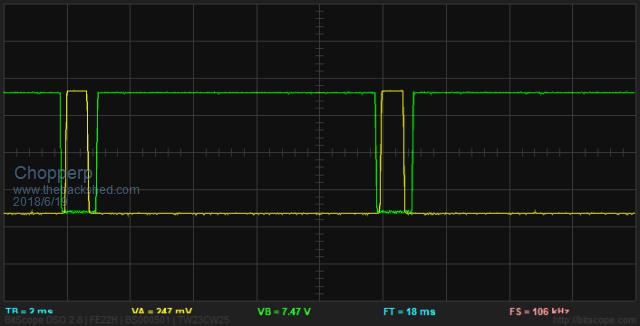 Oneshot Pulse occurring just after the trigger pulse. Near full power 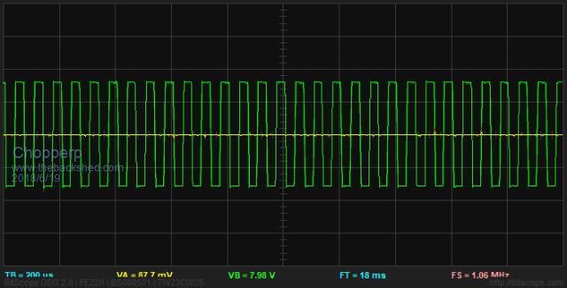 The PWM O/P Trigger signal (15000kHz) 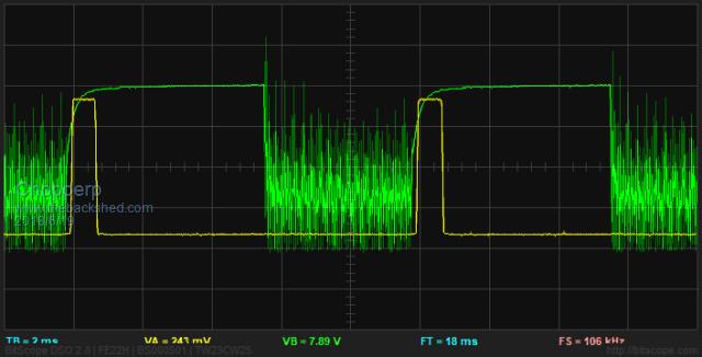 Combined (gated) Oneshot & PWM pulses at about 50% (inverted) 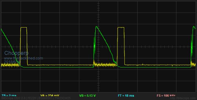 SCR output pulse at about 25% 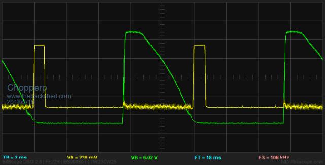 SCR Output at about 50%. Note flat top AC 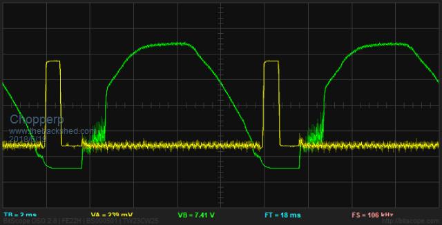 SCR Output at about 80%. ChopperP |
||||
| Warpspeed Guru Joined: 09/08/2007 Location: AustraliaPosts: 4406 |
Very nice ! Cheers, ĀTony. |
||||
| Chopperp Guru Joined: 03/01/2018 Location: AustraliaPosts: 1123 |
Thanks Tony ChopperP |
||||
| Warpspeed Guru Joined: 09/08/2007 Location: AustraliaPosts: 4406 |
I have a high power home made bench power supply I built a few years back using phase control. Switching power supplies may be the go these days, but for a very simple power supply, phase control is difficult to beat for simplicity and robustness, especially at very high power levels. Cheers, ĀTony. |
||||
| Chopperp Guru Joined: 03/01/2018 Location: AustraliaPosts: 1123 |
I would ideally like a 75V, 35A power supply unit to test the Loco's Voltage / current Regulator but that ain't going to happen (nearly 3kW). Would also need a corresponding dummy load. But I do have a work around for that so not critical. Try for the battery charger first.I made 12/24/36V, 20A phase control charger many years ago. Still works. Needs an overhaul though. ChopperP |
||||
| Zonker Guru Joined: 18/08/2012 Location: United StatesPosts: 772 |
Big thank you the everyone adding feedback to this thread..!!  The 6 pulse 3 phase scope work is "on hold" for now as it's "all hands on deck" to get out lot's of new job contracts at work...  As soon as I can get some head room, I will try and get the scope shots done... As soon as I can get some head room, I will try and get the scope shots done...Thanks again everyone...! |
||||
| Warpspeed Guru Joined: 09/08/2007 Location: AustraliaPosts: 4406 |
Chopper, all you really need is a suitable transformer and choke. An old fork lift battery charger for instance might be ideal if you can find on at a junk yard or auction. I built a Frankenstein bench power supply into an old computer case. 0 to 100v (+50v and -50v) at 25 amps. It just has a big knob and uses phase control on the mains side of the transformer. As rough as guts, no voltage regulation, no current limit. The main circuit breaker just pops if I have an "event" <grin>. 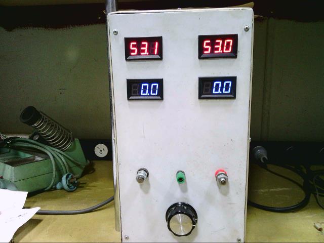 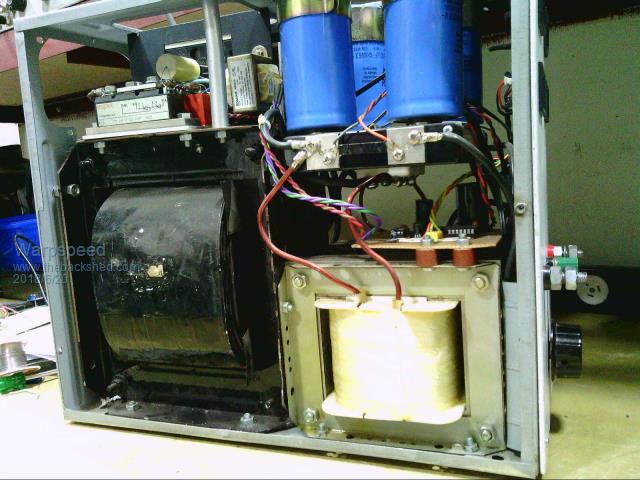 Cheers, ĀTony. |
||||
| Chopperp Guru Joined: 03/01/2018 Location: AustraliaPosts: 1123 |
@Zonker No worries mate!! I'm glad you raised the topic in the first place. You may need matherp to wield more Csub magic to get 6 pulses though if you go that way. @ WS Looks impressive.  I was going to ask you what you did for current limiting. A 2" nail by the looks of it . I thought I had some rectifier / thyristor blocks like you have up in the top LH corner, but just had a look & can't find them. Got a huge darlington transistor left though. Out of an old UPS. I was going to ask you what you did for current limiting. A 2" nail by the looks of it . I thought I had some rectifier / thyristor blocks like you have up in the top LH corner, but just had a look & can't find them. Got a huge darlington transistor left though. Out of an old UPS.What is your minimum load current before the choke stops choking. I assume it's a choke input arrangement? I have an old Lester 36V / 20A phase controlled charger I'm not using. It has a centre tapped secondary with an SCR in each leg. For a start, I might bridge the total secondary & put the SCR after that. (Don't like controlling the mains input though it would be more efficient). Not sure if it will have enough volts to have an input choke though. Should give me 10A. ChopperP |
||||
Azure Guru Joined: 09/11/2017 Location: AustraliaPosts: 446 |
@Warpspeed I like the old Weller in the corner, still have mine. Even though it does not get used much I dragged it out recently to lend to someone and it still works. |
||||
| Warpspeed Guru Joined: 09/08/2007 Location: AustraliaPosts: 4406 |
Chopper, Its a centre tapped transformer with a bridge rectifier. Two chokes, and two plus two 22,000uF 63v electrolytics to give me positive and negative supplies with respect to ground. This is a real junk box hot rod special, only things I had to buy for it were the digital panel meters and some 12v plug packs to supply dc to the control system and panel meters. I don't worry about fine details like like voltage regulation. Just wind up the wick until the load comes to life, and that is about it. Its only ever used for those quick dirty jobs.... The chokes were made for me by a long term mate that has a transformer winding business. I don't know what they are worth, this was a freebie return favor job. Each has a one and a quarter inch stack of two inch laminations with a 1.5mm air gap. There are 72 turns of 6mm x 2mm rectangular copper. No load inductance measures as 4.24mH It still has 3.07mH at 25 amps dc. If I ever did measure the saturation limit, its not on my now ancient scrap of paper in my file. Thought this might interest some of you blokes that probably have a mountain of similar old parts out in the shed just sitting around. Cheers, ĀTony. |
||||
| Chopperp Guru Joined: 03/01/2018 Location: AustraliaPosts: 1123 |
@Azure. I noticed that too. Still use mine. Got a couple of other dud ones as well (er). @Warpspeed I found my double SCR blocks. IRKT71-12 "SCR Modules 1200V 75A Doubler Circuit Positive Phase Control Thyristor/Thyristor". Look a tad different to yours. The transistors I mentioned are QM200HA-H; 200A @ 600V, 1200W, hFE of 75. Big ones. Thought I'd chucked them out. ChopperP |
||||
| Warpspeed Guru Joined: 09/08/2007 Location: AustraliaPosts: 4406 |
Those big dual SCR blocks are pretty indestructible. I have quite a few of them here, but no real use for them. Something like that can pop a 20 amp mains circuit breaker easily and never be harmed. Pretty ideal for a rough as guts big dc supply. Cheers, ĀTony. |
||||
| Chopperp Guru Joined: 03/01/2018 Location: AustraliaPosts: 1123 |
@Warpspeed. Missed your previous post. Thanks. I do have some old non working supplies with chokes in them in the 15 - 20A range. Will see how things pan out. Using a microprocessor, there are more things to go wrong. More versatility though. What were your particular reasons for using the chokes? ChopperP |
||||
| Warpspeed Guru Joined: 09/08/2007 Location: AustraliaPosts: 4406 |
Without chokes, the electrolytics always try to charge up to the peak voltage, and the current through everything takes the form of a very short very high current burst right at peak voltage. That stresses everything out, and creates much more heat and higher losses in the transformer and rectifiers. A choke once it gets going, at some minimum load current, cases an almost constant current to flow each half cycle through the rectifiers and transformer. Losses are much lower, heating much less, and the voltage regulation will be much better at high load. Cheers, ĀTony. |
||||
| Chopperp Guru Joined: 03/01/2018 Location: AustraliaPosts: 1123 |
Thanks Tony. The typical advantages of a choke input filter, I knew that. The thing you do lose, of course is the higher voltage but you do gain a higher current. I could never work out how you got the constant current throughout the cycle. When I did this sort of stuff at Uni ages ago, they drew square wave graphs for current flow. Had me confused. (Which is easily done). Just took their word for it. Plenty of experimenting to do with the junk, I mean stuff I have. We probably should be over on the Electronics Forum with this, but the lines are blurred these days. Brian ChopperP |
||||
| Warpspeed Guru Joined: 09/08/2007 Location: AustraliaPosts: 4406 |
It would be square waves if the choke was infinite. The other thing you gain is a lower output ripple voltage, especially at high current. Its just an all around better way to do things. Cheers, ĀTony. |
||||
| Chopperp Guru Joined: 03/01/2018 Location: AustraliaPosts: 1123 |
Thanks. Just been up in the attic & found some old Uni books. One on Power Electronics. Bit of Bedtime / Loo reading ChopperP |
||||
| The Back Shed's forum code is written, and hosted, in Australia. | © JAQ Software 2026 |
