
|
|
Forum Index : Microcontroller and PC projects : uM2(+): Constant Current/Voltage PSU
| Author | Message | ||||
centrex Guru Joined: 13/11/2011 Location: AustraliaPosts: 320 |
I have one PCB left if anyone wants it pm me, $5ea plus postage. Cliff edit All the boards have now been spoken for. Thanks Cliff Thanks Peter for the setup info much appreciated. Cliff |
||||
| Emady Newbie Joined: 02/02/2016 Location: United KingdomPosts: 23 |
Thanks for the reply, so would the input voltage have an effect on the output voltage then? If not then I would probably use a 9V supply which should limit the heat output to less than 10W or am I talking nonsense... |
||||
| matherp Guru Joined: 11/12/2012 Location: United KingdomPosts: 11608 |
Totally depends on the output voltage you want. The maximum will be 3V or so below the input voltage. If you don't need an output >6V then 9V is fine |
||||
plover Guru Joined: 18/04/2013 Location: AustraliaPosts: 306 |
I now have 2 pcbs in my hands, and various other main components in the mail. I think I have obtained Schematic and layout information needed as well. I will have to get displays on order and find that there are a number which to me looks the same. With driver IC ILI 9341, is the following a safe bet? http://www.ebay.com/itm/2-8-Inch-240x320-Serial-SPI-TFT-Screen-LCD-PCB-Board-Driver-IC-ILI9341-For-5110-/181625077737 2.8"Inch 240x320 Serial SPI TFT Screen LCD+PCB Board Driver IC ILI9341 For 5110 |
||||
bigmik Guru Joined: 20/06/2011 Location: AustraliaPosts: 2981 |
Hi Plover, Hopefully your chips arrive soon, they were posted last week (OK .... LATE last week).. That display doesn't look like it has a touch screen fitted... This one looks to be the unit you need.. SPI Touch Panel Regards, Mick Mick's uMite Stuff can be found >>> HERE (Kindly hosted by Dontronics) <<< |
||||
| plover Guru Joined: 18/04/2013 Location: AustraliaPosts: 306 |
bigmik Thanks, my lucky day placing the post, I think my sixth sense helped me. Havfing no experience with these screens I have no idea what to look for. Nice little uplifting bit to have been saved from getting it wrong. I unexpectedly got stuck all Sunday in trying to debug my Android Phone. I had told my wife any phone could play mp3 files, then to find I could not get my android phone to do that, was loss of face. I got rather intrigued because on a simple Telstra phone for my neighbour, non android of course, I took the SD card out and put 8GB of songs on it and it is now pensioned off as mp3 player. Tried the same trick on Android and the fun began.  |
||||
| matherp Guru Joined: 11/12/2012 Location: United KingdomPosts: 11608 |
ERRATA I've just built up the complete PCB by moving the components from my prototype. There is one silkscreen error. The resistor shown in the picture is marked as 10K but should be 18K 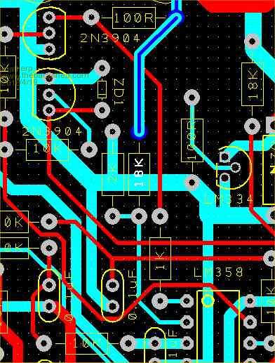
Other than that the board works perfectly. Note R25 and R47 should be 100K as per the schematic. For some reason the value didn't make it to the silkscreen. |
||||
| MicroBlocks Guru Joined: 12/05/2012 Location: ThailandPosts: 2209 |
Can you look which package of the LM334Z you have, they seem to come in many varieties. Want to be sure i order the right one (which follows the pcb layout). Microblocks. Build with logic. |
||||
| centrex Guru Joined: 13/11/2011 Location: AustraliaPosts: 320 |
Hi Peter How critical is the resistor I have built the board with the components as marked, difficult to remove components from plated through holes. Just wondering is this the board I sent you. Regards Cliff. Cliff |
||||
| matherp Guru Joined: 11/12/2012 Location: United KingdomPosts: 11608 |
This one Critical I'm afraid - this resistor sets the opamp gain. To remove just heat one pad with the soldering iron and then pull that end of the resistor with a finger nail. Then hold the resistor and heat the other pad to remove. To clear the holes heat with the soldering iron on one side of the board and then with your mouth close to the other side of the board (but not too close  ) blow hard as you remove the soldering iron - this will leave the hole clear for re-use. ) blow hard as you remove the soldering iron - this will leave the hole clear for re-use.
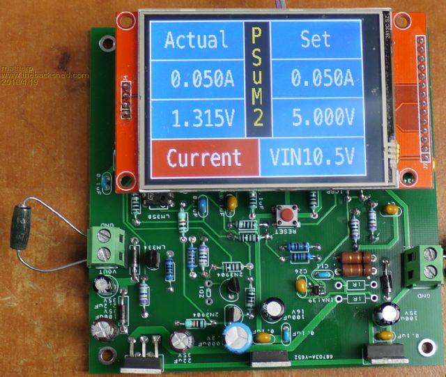
Bug in code There is a line missing in the initialisation DriveAmps=SetAmps-LowAmpAdjust
should appear just after VAR RESTORE e.g. VIN=pin(VIN_ADC)*VIN_CAL+diode 'get input voltage for first output voltage validation
VAR RESTORE 'restore voltage and current set values if previously set DriveAmps=SetAmps-LowAmpAdjust if SetVolts > VIN-dropout then SetVolts=VIN-dropout ' ensure set voltage is valid ' ' Main program ' Without this the power supply won't generate output after powering on until after the current is explicitly set by the user Here is my board up and running - thanks Cliff 
|
||||
| MicroBlocks Guru Joined: 12/05/2012 Location: ThailandPosts: 2209 |
@Matherp, I am busy with laying out a small pcb. I like to mostly use SMD parts. Looking at the resistors i noticed that many of them will not have much current going through them and it would be possible to use a 0.1w smd versions. Higher wattage is difficult to source. Could you help me out and specify which resistors would absolutely need to be 0.25w. The 1 Ohm current sense resistors i already have 1W versions and also for the backlight i am using a 0.5w. I am just wondering which of the rest that are currently 0.25w could be substituted with a 0.1w. I am also going to use it up to maximum 16v/1A output using a 19v input, if that will make a difference. Would that be a 27 Ohm resistor as the load? Maybe a nice add on feature to measure resistance, with a low enough current set it would be save to do. This is my progress so far (50x50mm) 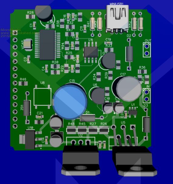
Microblocks. Build with logic. |
||||
| matherp Guru Joined: 11/12/2012 Location: United KingdomPosts: 11608 |
0.1W is probably fine for all the others except perhaps the 10 ohm resistor feeding AVDD. You would have to look up requirements for AVDD in the Microchip datasheet Yes That is doable, you could also display power. I'll leave it up to all you good folk to add features to the Basic code as you wish |
||||
| centrex Guru Joined: 13/11/2011 Location: AustraliaPosts: 320 |
Hi Peter Would you be able to update the schematic and the Gerber's for the power supply to the current detail. My board is working quite well although I have to go through the full calibration, job for the weekend. Cliff Cliff |
||||
| matherp Guru Joined: 11/12/2012 Location: United KingdomPosts: 11608 |
These should now be consistent. There are no wiring changes just value/labelling. I have however also added an extra hole for each of the electrolytic caps so you can now use a 5mm lead-spacing device or a 2.5mm 2016-04-21_074855_PSuM2V11.zip |
||||
| bigmik Guru Joined: 20/06/2011 Location: AustraliaPosts: 2981 |
Hi All, I just bought one of These Cases and I think it would make a decent case for the PSU. You probably could mount the Laptop charger inside as well. Kind Regards, Mick Mick's uMite Stuff can be found >>> HERE (Kindly hosted by Dontronics) <<< |
||||
| centrex Guru Joined: 13/11/2011 Location: AustraliaPosts: 320 |
I have the power supply running and calibrated as best I can. 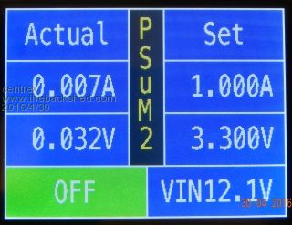
I have noticed a couple of things....... There appears to be a residual voltage and current shown on the display and it also appears across the 10 ohm load measured with a multimeter this is with the unit "OFF". Also if I turn off the supply to the unit, when I turn the supply back on I have to reset the current section otherwise it goes direct to the current limit mode. Perhaps this is normal, maybe Peter can give an answer. Other than the above it works very well I am most pleased. Cliff Cliff |
||||
| matherp Guru Joined: 11/12/2012 Location: United KingdomPosts: 11608 |
PWM is switched off when in this mode so it must be that the 0V output of the uP is very slightly above GND. If you are worried about it I can only suggest putting a relay in-line with the output and switching it with a spare uP pin driving a NPN transistor. This is the bug I posted a fix to in the second post of page 5 of the thread |
||||
| centrex Guru Joined: 13/11/2011 Location: AustraliaPosts: 320 |
Thanks Peter, it such a low amount it does not worry me just for interest. I will double check that I have the required change to the program. Thanks it is a great device. Cliff |
||||
| centrex Guru Joined: 13/11/2011 Location: AustraliaPosts: 320 |
All fixed thanks Peter that will teach me to read all the posts. Cliff |
||||
| Spacedementia87 Newbie Joined: 03/08/2016 Location: United KingdomPosts: 26 |
Hello, Thanks for this. It looks great and I am just working my way around the schematics ensuring I understand it before breadboarding it up. I will start by breadboarding the PS circuit without the screen or microcontroller to check it all works! Couple of Q's though. 1. There are a few capacitors and diodes without values. Does the value not matter in these cases? Seems odd. Should I have 0.1 nF or 12,000uF? 2. Would an ATmega chip work as a replacement for the micromite? I already have an act programmer etc... Setting up be be able to program a micromite is quite a bit more up front. Thanks for all the good work! |
||||
| The Back Shed's forum code is written, and hosted, in Australia. | © JAQ Software 2026 |
