
|
|
Forum Index : Microcontroller and PC projects : MM+, Explore 64 and Explore 100
| Author | Message | ||||
| robert.rozee Guru Joined: 31/12/2012 Location: New ZealandPosts: 2542 |
a word of caution - thre are at least two different type of rechargable lithium button cells out there: 1. a 3v lithium cell similar to a CR2032, but designed to be trickle charged continuously at an extremely low current, in the region of a few hundred microamps. one such example is this one: http://www.produktinfo.conrad.com/datenblaetter/250000-274999/252238-da-01-en-KNOPFZELLENAKKU_3V_CR2032.pdf in fact, a normal CR2032 cell can be trickle charged very slowly, i recall currents around 10uA are considered safe. 2. a 3.6v lithium ion cell, supporting relatively high charge currents but requiring the same sort of charge regulation as any other lithium ion cell. constant-cirrent, constant-voltage, with a charging timeout and possibly temperature monitoring. i've just had a look at one of the RTC modules i have here, and it has a 200 ohm resistor in series with a diode. assuming a Vcc of 5v, that would produce a charging current of (5.0 - 3.6 - 0.6)/200 = 4mA or thereabouts, delivered continuously. this would be ill-advised for either of the above cell technologies. there will be no fire, unlikely to be a pop, but nonetheless not a long cell life. given the miniscule current draw of an RTC, i would advise (after removing the resistor and diode) to stick with a normal CR2032 cell that you replace every 10-15 years. cheers, rob :-) |
||||
mikeb Senior Member Joined: 10/04/2016 Location: AustraliaPosts: 180 |
@Grogs Don't sweat it. I've been married for 32 years  It got me out of the house. It got me out of the house.
I scraped between each pin as far as I could behind the pins (past the pin lands). I couldn't see any bridge either.  I like fault finding anyway. I like fault finding anyway. 
Nice little design. I thought $ 75-00 dollars was good value regardless. To save some 'legwork' do you have any 'Option' strings we can 'copy and paste', at the command prompt, when setting up the screen and touchpanel ? Also, I believe the 'Read Pin' is connected to pin 6 of the PIC32. Correct ? Thanks very much for your efforts. I'm sure we all appreciate it. 
@robert.rozee I'm with you. Can't see the point of having a rechargeable battery considering a standard lithium cell will last its 'shelf life'. There are 10 kinds of people in the world. Those that understand binary and those that don't. |
||||
Grogster Admin Group Joined: 31/12/2012 Location: New ZealandPosts: 10005 |
Hi - thanks for your understanding.  I was SURE I did not send any out with bridges, Hopefully yours is the only one..... I was SURE I did not send any out with bridges, Hopefully yours is the only one..... 
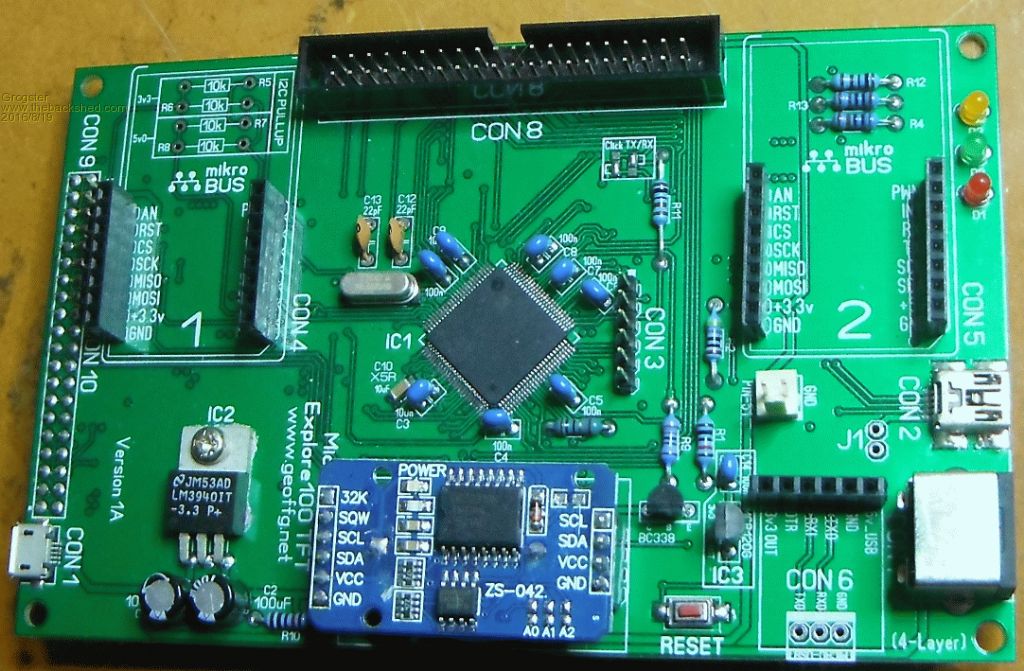
No "Option strings" to paste at the command prompt, but if others thought this would be useful, I could certainly make a post along those lines - or start another thread with it in it, so you could save. Generally speaking, it is left up to the user to decide what they want to configure and how. As to pin6, RD - yes - correct: 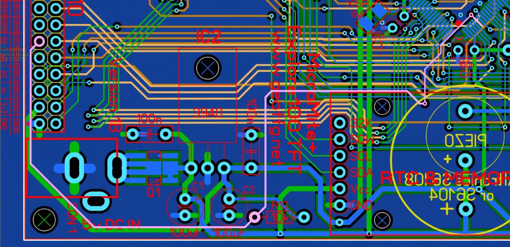
The pink line is the highlighter tool for testing connections. RD is also pulled-up to 3v3 via R10. Smoke makes things work. When the smoke gets out, it stops! |
||||
| mikeb Senior Member Joined: 10/04/2016 Location: AustraliaPosts: 180 |
@grogster Sorry to be unclear but I was referring to 'option' strings relevant to your board. The schematic makes no reference to signal names, regarding the touchscreen connector, so requires the user to count pins on the schematic and relate this to the touchscreen connector. Just thought it might limit future threads when things don't work. As you must have a working board I thought you might have saved strings somewhere. I tend to save 'option' strings in a text file, for later retrieval, should the need arise. It eliminates the possibility of 'typos'. There are 10 kinds of people in the world. Those that understand binary and those that don't. |
||||
| Grogster Admin Group Joined: 31/12/2012 Location: New ZealandPosts: 10005 |
Oh, right, I see what you are getting at. I think this is all covered in the next few SC issues. If not, I can certainly make a chart for which pins are the touch etc. Smoke makes things work. When the smoke gets out, it stops! |
||||
| Zonker Guru Joined: 18/08/2012 Location: United StatesPosts: 772 |
Well... It looks like the E-100 package just popped in on the post and seems to good condition... Nice packaging job G..!! To late to warm up the soldering station tonight, but will have a go at it after work tomorrow... Is there a schematic PDF for the unit..? Maybe I missed it... (will poke around to find it)... I remember reading the part about getting the reset IC fitted correctly... I think I also have the 4.3" display that fits correctly for it... (I still like the "Big 7") 
Very nice layout Grogs..!! |
||||
| mikeb Senior Member Joined: 10/04/2016 Location: AustraliaPosts: 180 |
@grogster Don't worry too much about it. I'll just take a harder look at the schematic and correlate that to the touchscreen and then make my own string. Just wanted to save the legwork. There are 10 kinds of people in the world. Those that understand binary and those that don't. |
||||
| Grogster Admin Group Joined: 31/12/2012 Location: New ZealandPosts: 10005 |
@ Zonker - thank you for you kind word.  I am glad you are pleased. YES, there is a schematic in the E100 constructor pack, which I believe is linked to a few pages back on this thread. I am glad you are pleased. YES, there is a schematic in the E100 constructor pack, which I believe is linked to a few pages back on this thread.
@ mikeb - If you get SC magazine, I have no doubt this will be covered in the next issue. Quick reference is: LCD_RS = Pin 18 LCD_WR = Pin 19 LCD_RD = Pin 06 (with external 10k pull-up) LCD_RST = Pin 42 TOUCH CS = Pin 01 TOUCH/SD CLK = Pin 10 TOUCH/SD DIN = Pin 12 TOUCH/SD DOUT = Pin 11 TOUCH IRQ = Pin 40 F_CS = Pin 58 (SPI flash memory chip CS) F_CS on Pin 58 is NOT available on the 1A boards, but very few people have those(only the alpha board testers). Smoke makes things work. When the smoke gets out, it stops! |
||||
| Phil23 Guru Joined: 27/03/2016 Location: AustraliaPosts: 1667 |
100%. Even Eneloops, which are the better of the NiMh rechargeable, are less likely to perform in long term low current applications. Great when you want them to have their long shelf charge & good performance in service. But for low drain situations like say a TV remote, just normal Alkaline perform much better. Think I put LIR2032's Vs CR2032's in the same basket. 3 times the cost & probably bound to fail prematurely if not correctly maintained. Cheers. |
||||
| mikeb Senior Member Joined: 10/04/2016 Location: AustraliaPosts: 180 |
@Grogster Thanks for the list. That will do nicely. There are 10 kinds of people in the world. Those that understand binary and those that don't. |
||||
| Phil23 Guru Joined: 27/03/2016 Location: AustraliaPosts: 1667 |
Well it Boots up! Con9; LCD. Wondering what most are doing with it? On the top or the bottom of the board. Blindly put my first on top (5pm after the 3am start). Then realised if it was on the bottom it could be more of a backpack configuration when used with a 5" screen. Curious what others think. Other thing I wondered is; Anything unique about pin 51, the way it's on it's own with a ground. (Has that Area 51 intrigue). Cheers. Phil. PS. Compliments to all involved in it's design. Nice board. |
||||
| Grogster Admin Group Joined: 31/12/2012 Location: New ZealandPosts: 10005 |
LOL! - I love your Area-51 reference, Mulder.
Pin-51 is input-only, and was spare, so it was routed out to that header along with a ground pin, just so you can use Pin-51 if you want to. Better to route it out then leave it buried in the 0.5mm pin-pitch, then people can at least use it if they want to. CON9 - Female header is meant to mount on the same side as the Piezo, so that you can plug an LCD directly on to the back of it. That is how it was designed to stack anyway. You COULD put a box-header on the top side, and use a ribbon-cable to link to the LCD if you prefer. Smoke makes things work. When the smoke gets out, it stops! |
||||
| Phil23 Guru Joined: 27/03/2016 Location: AustraliaPosts: 1667 |
Hmmmm, Wondered the when I finished welding.... Con 9; Don't fancy my chances of removing it. Should work though if I hang the LCD off the left side though. Did look twice & figured the box was drawn on top, but the 3am start was setting in pretty well by then. The 3am start is for I'm for sure what? Brain overload I think; "What is it I need to do today"? Phil. |
||||
| Phil23 Guru Joined: 27/03/2016 Location: AustraliaPosts: 1667 |
Also RTC? Are most soldering them direct with header pins at both ends? Or socketed? Cautious about how trustworthy the cheap RTC modules are. |
||||
| Phil23 Guru Joined: 27/03/2016 Location: AustraliaPosts: 1667 |
Ugggggh, Realise flipping would only work with a SIL connection, not DIL. To-morrow... |
||||
| Grogster Admin Group Joined: 31/12/2012 Location: New ZealandPosts: 10005 |
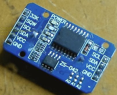
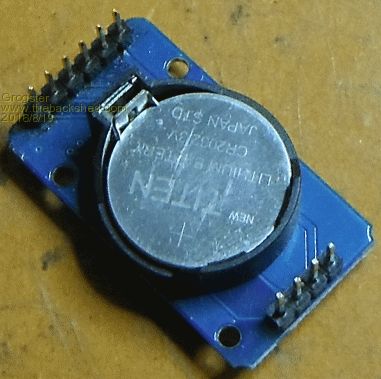
You're right - the box around CON9 on the top is a little confusing. I will remove that in any future version of the board, and make sure that is on the other side. Female headers on the RTC, and you remove the right-angled pin-strips on the eBay-type RTC module, and replace them with straight pins, and then the RTC can plug directly into the board. Some photos might help: 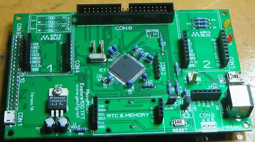

Smoke makes things work. When the smoke gets out, it stops! |
||||
| Phil23 Guru Joined: 27/03/2016 Location: AustraliaPosts: 1667 |
Anyone got an "Idiot Hat" I can borrow? Other thing I notice, the Jaycar Piezo I've got on the E64 doesn't seem to have any polarity markings. |
||||
| Grogster Admin Group Joined: 31/12/2012 Location: New ZealandPosts: 10005 |
I've got one of those hats. It's almost worn out though, from as many times as I have had to wear it myself, so it is probably of no use to you.
Don't concern yourself. It can't have been perfectly clear, or you would not have had any doubt about any of this. Smoke makes things work. When the smoke gets out, it stops! |
||||
| Grogster Admin Group Joined: 31/12/2012 Location: New ZealandPosts: 10005 |
You can use the likes of Chip-Quik to aid in the removal of the header. This stuff is brilliant, and well worth the money, even though it does not look like you get much for the price. You melt this stuff all over the connector so that all pins are bridged with it, keeping moving the iron around to keep the Chip-Quik in a melted state, then you just easily flick the socket or IC or whatever off the board. Soak up the leftover with braid wick, then re-drill the holes, refit the socket and all is well with the world again.
Out of the various SMD or removal tools I have tried, I have to say that I still like this low-melting-point Chip-Quik solder the best of all. EDIT: EEVblog talking about it and using it. Smoke makes things work. When the smoke gets out, it stops! |
||||
| robert.rozee Guru Joined: 31/12/2012 Location: New ZealandPosts: 2542 |
for the misplaced connector, use a pair of snipe-nosed pliers to grab the pins one at a time, heat pin and pull out. the connector will be somewhat destroyed, but the PCB will be unharmed. then use solderwick to empty out the holes, or just heat and tap GENTLY on the edge of your bench (my preferred method). edit: i was looking at the connector on the top edge of the board. i would still favour destroying the RHS connector (though this will be a bit harder) so that the pins can be removed one-by-one. unless the piezo is active (ie, a fixed frequency device containing a transistor oscillator and driven by DC), it will be unpolarized. the housings often have a polarity mark simply because it is cheaper for the manufacturer to make just the one type of housing and use it for both active and passive devices. the 4 pins on one end of the RTC module are passthroughs from the 4 similarly marked pins at the 6-pin end. grogster: might i suggest removing the text markings from the 4-pin end on the next revision of the board, as these pins are just being used for mechanical support? cheers, rob :-) |
||||
| The Back Shed's forum code is written, and hosted, in Australia. | © JAQ Software 2026 |
