Notice. New forum software under development. It's going to miss a few functions and look a bit ugly for a while, but I'm working on it full time now as the old forum was too unstable. Couple days, all good. If you notice any issues, please contact me.
Quazee137 Guru Joined: 07/08/2016 Location: United StatesPosts: 603
Posted: 07:04am 31 Oct 2017
Copy link to clipboard
Print this post
I guess I did not understand that the switch was on a long wire. One last idea here I always keep long wires isolated from my main chips.
Grogster Admin Group Joined: 31/12/2012 Location: New ZealandPosts: 9975
Posted: 12:01pm 31 Oct 2017
Copy link to clipboard
Print this post
The ball-switch is not on a long-wire. It is about 10mm from the input pin, soldered directly to the PCB.
I totally agree with you about the opto-couplers though. I use them for anything that needs a wire to a switch. I never run the wire to the switch, then back to the MCU input pin, as that arrangement is fantastic for false-tripping. The long cable runs act like aerials on the inputs, and the poor old MCU has a coronary trying to decide which state the pin is in.
I have been experimenting with a 1k pull-up to the I/O pin on the ball-switch, and it seems to be working well. At 3v3, when the ball-switch closes, this results in about 3.3mA flowing to ground, which is much higher then the approximately 60uA without the pullup and using the internal pullup option in the code. This 3mA or so seems to be blasting through any oxide layer in the ball-switch, and I am getting very reliable tripping now, and only when tilted as it should be.
Yes, this will suck a bit more from the battery, but as soon as the ball-switch opens, this current flow stops, and also the MCU goes back to sleep. So, it will affect the battery life to some extent, but I am happy that it should still be perfectly acceptable. Original design had a battery life in standby of more then two weeks without a charge, so I would still expect the best part of one week without charge.
Will post back here if the situation changes!Smoke makes things work. When the smoke gets out, it stops!
Quazee137 Guru Joined: 07/08/2016 Location: United StatesPosts: 603
Posted: 03:24pm 31 Oct 2017
Copy link to clipboard
Print this post
One last ditch to fix the cause can you gold plate the ball and cups?
Boppa Guru Joined: 08/11/2016 Location: AustraliaPosts: 816
Posted: 09:11pm 31 Oct 2017
Copy link to clipboard
Print this post
Ah the good old acrifix- horrible smell and dont get it on your skin, but works wonders on plastics!
Another use for it is when you get O/C cells on solar panels, we used to use it to fix up after repairs- depending on whether it was soft or hard plastic over the cells Most at the time were a softish plastic that could be cut gently down to the cell surface with a sharp exacto knife, resolder the repair or bridge cell with thin enameled wire and acrifix it up afterwards, hard plastics were melted through with an old soldering iron kept just for that job
Paul_L Guru Joined: 03/03/2016 Location: United StatesPosts: 769
Posted: 12:49am 01 Nov 2017
Copy link to clipboard
Print this post
Gold plating seems a bit much. If the ball and contacts are steel or copper then maybe a nickel or silver plate or even just a tin or solder coat would reduce corrosion.
CaptainBoing Guru Joined: 07/09/2016 Location: United KingdomPosts: 2171
Posted: 07:04am 07 Nov 2017
Copy link to clipboard
Print this post
I have had it with PULLUP(?)
I read followed this post over the weeks and now I seem to have been bitten too!
Seems innocuous enough? It is for two push-button switches that pull to GND when activated. So why is it that when I press the DoorDown switch (and only that one - wired to Pin 3), the MM (170B 5.04.04) resets... clock, everything but no exception reported or anything else - just the start-up banner (triple checked the wiring - all good). I don't even have any code looking at these two pins yet!
So, thinking it might not like the SPI OUT pin being used as an i/p, what with being dragged to ground and all, I move the switch to pin 6. Same thing!
Remembering this thread, I REM out the PULLUP property of the set pin... bingo! No reset.
I've run out of time but I will put separate pullup resistors on the pins this week and try from there.
If this proves OK, I am loathe to use PULLUP/DOWN anymore coz the tolerances etc in the chip seem so unpredictable. Anyone?
Grogster Admin Group Joined: 31/12/2012 Location: New ZealandPosts: 9975
Posted: 11:43am 07 Nov 2017
Copy link to clipboard
Print this post
Well, from past experience and what others have said, the internal pullup that is enabled by the PULLUP option appears to be somewhat vague as to what the value actually is. Initially, it was reported as being 100k, but this now seems to have been revised and people now suggest that it is more in the area of 47k-ish.
I too have elected to simply not use that option anymore, and I will go back to the tried and tested method of a 10k/1k arrangement to Vcc or ground(depending on which way you want to pull the input pin).
The external pull-up/pull-down resistors have NEVER let me down, and is a method I am happier with anyway as it prevents the pin floating. The pin should not be floating with the PULLUP option, but the input still seems to do odd things with that in place.
Since I added the usual 10k/1k external pull-up resistors to my problem child in this thread, the problem has essentially vanished. A lesson to be learnt there I think...Smoke makes things work. When the smoke gets out, it stops!
Alastair Senior Member Joined: 03/04/2017 Location: AustraliaPosts: 161
Posted: 12:37pm 07 Nov 2017
Copy link to clipboard
Print this post
I have just received back from China bundle of pcbs in which I have relied on the pullup/dn resistors quite a bit. I think I will do an experiment using say a 10k resistor to Vcc/Gnd on some E28 pins and then use pullup/dn option and see what voltage the pins go to. The voltage division should give an idea of what the internal value is. Is this valid? Can't see why not. Cheers, Alastair
Warpspeed Guru Joined: 09/08/2007 Location: AustraliaPosts: 4406
Posted: 01:20pm 07 Nov 2017
Copy link to clipboard
Print this post
Yes, or you can just measure the current with a multimeter from input pin to ground. For example 5v and 100K pullup = 50uACheers, �Tony.
Alastair Senior Member Joined: 03/04/2017 Location: AustraliaPosts: 161
Posted: 01:55pm 07 Nov 2017
Copy link to clipboard
Print this post
Tony, Yep. I will do all 4 permutations of resistor, current, up, dn. Bet I don't get the same answers. Cheers, Alastair
redrok Senior Member Joined: 15/09/2014 Location: United StatesPosts: 209
Posted: 02:15pm 07 Nov 2017
Copy link to clipboard
Print this post
Hi Alastair;I don't think the PU/PD resistors are real resistors. They are most likely "Partially Depleted" MOSFETs. MOSFETs like this operate the same as regular MOSFETs but the ON resistance is fairly high resistance. (One could call them kind of purposely made "Defective".)
Since your going to do some tests I would suggest using several test resistors values to see what the PU/PD resistance is at different pin voltages. I suspect the PU/PD values vary depending on the delta voltage across them.
It would be nice to see all your data on several different pins.
redrokEdited by redrok 2017-11-09
Alastair Senior Member Joined: 03/04/2017 Location: AustraliaPosts: 161
Posted: 06:09pm 07 Nov 2017
Copy link to clipboard
Print this post
Redrok, Your wish is my command.
Once I started I decided that since I was doing it I might as well do it properly because I thought exactly what you said. I used one of Grogster's E28 boards.
Voltages measured with a 10M input voltmeter. Resistance values in K
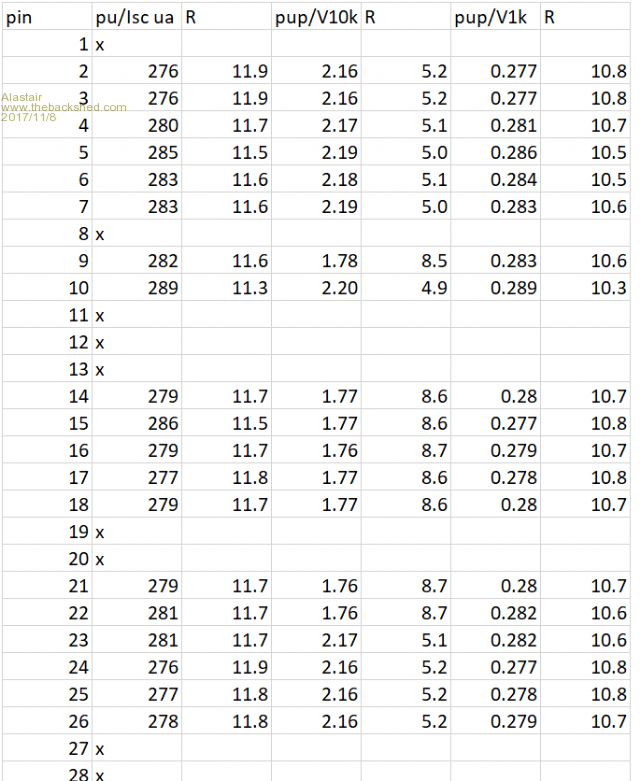
So the following table is Column C is Isc the short circuit current in ua for each pin with the pins set as DIN, PULLUP. The OC voltage was 3.27 so col D is the calculate pull resistance. Col E is the voltage across a 10K resistor, pin to Gnd and col F is the calculated resistance. Col G and H is the same thing for a 1K resistor.
C D E F G H
The table shows a fairly constant Pup res on the basis of the SC current of about 12K. The variation I would assume to be due to the location on the die. Pin 9 is an outlier probably due to the chip structure.The results using the the voltage divider results shows similar variation but quite different values which are almost certainly due to the mosfet load.
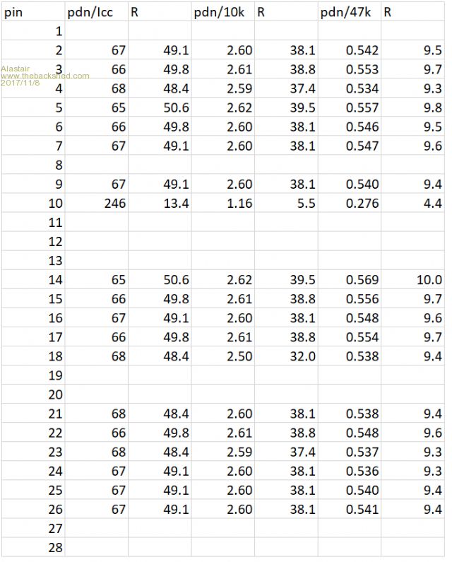
**************************************************************************** The following table is Column K is Isc the short circuit current in ua for each pin to Vcc with the pins set as DIN, PULLDOWN. The OC voltage was 3.29 so col L is the calculate pull resistance. Col M is the voltage across a 10K resistor, pin to Vcc and col N is the calculated resistance. Col O and P is the same thing for a 47K resistor.
K L M N O P
The results for the Pdn case show a similar pattern but this time the resistance determined by the current approach is much higher. The voltage divider approach shows how the effective resistance changes greatly due to load. This time the outlier is pin 10. I did think of testing another E28 to see if things were different but have better things to do.
To me it says don't use the internal resistors but use external ones if it really matters. I now have to edit a pcb layout and have the boards remade. Grrrrrrrr
PS sorry the column headers got squashed by the white space cruncher. Edited by Alastair 2017-11-09Cheers, Alastair
redrok Senior Member Joined: 15/09/2014 Location: United StatesPosts: 209
Posted: 08:20pm 07 Nov 2017
Copy link to clipboard
Print this post
Hi Alastair;
I did a test also. I used 10 10K resister in a string on just P2 of an Explor28 I did it a bit different by only measuring the voltage and calculating the current.
Measurements done on P2 of an EXPLORE 28 VDD 3.296 V Meter R 10,000,000 O Meter PullUp PullUp PullUp PullDn PullDn PullDn Measured Resistance Corrected R Pin V Current Restance Pin V Current Restance 9,943 O 9,933 O 2.136 V 215.04 uA 5,394 O 2.629 V 67.15 uA 39,152 O 19,877 O 19,838 O 2.666 V 134.39 uA 4,688 O 1.965 V 67.09 uA 29,287 O 29,800 O 29,711 O 2.860 V 96.26 uA 4,529 O 1.320 V 66.51 uA 19,848 O 39,708 O 39,551 O 2.960 V 74.84 uA 4,490 O 0.760 V 64.12 uA 11,853 O 49,628 O 49,383 O 3.021 V 61.17 uA 4,495 O 0.523 V 56.15 uA 9,314 O 59,575 O 59,222 O 3.063 V 51.72 uA 4,505 O 0.411 V 48.71 uA 8,437 O 69,540 O 69,060 O 3.093 V 44.79 uA 4,533 O 0.344 V 42.75 uA 8,048 O 79,463 O 78,837 O 3.115 V 39.51 uA 4,581 O 0.295 V 38.07 uA 7,750 O 89,414 O 88,622 O 3.133 V 35.35 uA 4,611 O 0.259 V 34.27 uA 7,558 O 99,357 O 98,380 O 3.147 V 31.99 uA 4,658 O 0.230 V 31.17 uA 7,380 O
The resistance varies all over the place. I see you did it for all the pins and there is quite a variation between pins.
I looked at the spec and get the "Inpression" that MicroChip discourages the use of the weak pullups for anything that needs fast speed especially with interrupts. There are a bunch of "Note 6" references on many of the specifications.
I suppose the weak pullups are useful for holding unused pins so they don't float.
They do have a paragraph that suggests week pullups can be used with switches and keypads.
I guess external pullups with known stable values are the way to go for reliable operation.
redrokEdited by redrok 2017-11-09
Alastair Senior Member Joined: 03/04/2017 Location: AustraliaPosts: 161
Posted: 10:52am 08 Nov 2017
Copy link to clipboard
Print this post
@Redrok, Your numbers are consistent with mine.
Lot of fiddling but it was worth it as a one off. I won't use the internal resistors except for just stopping floating DIN pins when connected to other logic pins. I have used them in the past like this and not had problems. I was under the impression from the wording of the specs that the resistors were of a more stable value and just varied chip to chip.
@Grogster The last table shows what you had - a pull down resistance of about 50K, not enough whetting current for the ball switch I presume. Edited by Alastair 2017-11-09Cheers, Alastair
Grogster Admin Group Joined: 31/12/2012 Location: New ZealandPosts: 9975
Posted: 12:08pm 08 Nov 2017
Copy link to clipboard
Print this post
Very interesting facts there. Thanks for doing those tests, gentlemen.
[Quote=Alastair]@Grogster The last table shows what you had - a pull down resistance of about 50K, not enough whetting current for the ball switch I presume.[/Quote]
As you say......
[Quote=Alastair]To me it says don't use the internal resistors but use external ones if it really matters. I now have to edit a pcb layout and have the boards remade. Grrrrrrrr[/Quote]
Grrrrr indeed. I am in the same situation if it makes you feel any better. Pain in the arse.
Oh well. Faeces occurs.
[Quote=redrok]I don't think the PU/PD resistors are real resistors. They are most likely "Partially Depleted" MOSFETs. MOSFETs like this operate the same as regular MOSFETs but the ON resistance is fairly high resistance. (One could call them kind of purposely made "Defective".)[/Quote]
I was particularly interested in that observation. Changes things quite a bit if they are not really resistors at all.
Live and learn. Back to the two resistor method from now on.Edited by Grogster 2017-11-09Smoke makes things work. When the smoke gets out, it stops!
matherp Guru Joined: 11/12/2012 Location: United KingdomPosts: 11513
Posted: 12:49pm 08 Nov 2017
Copy link to clipboard
Print this post
From the MX170 manual, page 263Edited by matherp 2017-11-09
Warpspeed Guru Joined: 09/08/2007 Location: AustraliaPosts: 4406
Posted: 12:53pm 08 Nov 2017
Copy link to clipboard
Print this post
Those internal pullups are probably fine to stop a wandering input pin that has nothing connected to it. As soon as there are some tracks or long wires added to that pin in a noisy environment, we might be in trouble.Cheers, �Tony.
Grogster Admin Group Joined: 31/12/2012 Location: New ZealandPosts: 9975
Posted: 02:15pm 08 Nov 2017
Copy link to clipboard
Print this post
@ matherp - and there you have it.
@ warpspeed - Indeed. I have used the PULLUP thing with great success for pins that have a DIP switch or solder-blob pads on them to configure the chip at power up. However, once the pins are read, the code never refers to those pins again, so that is probably why those ones don't give any issues.Smoke makes things work. When the smoke gets out, it stops!
Grogster Admin Group Joined: 31/12/2012 Location: New ZealandPosts: 9975
Posted: 04:09pm 10 Nov 2017
Copy link to clipboard
Print this post
As a little update for this thread, I have disabled ALL the pullup options on all the units, but we are still getting issues with the ball-switch not tripping.
I have hacked one unit, and installed the standard 10k/1k from Vcc to the I/O pin. The ball-switch will not trip the unit, but holding a breadboard jumper wire across the switch DOES trip it.
I think these ball-switches are not as great an idea as I first thought.
Beleive it or not, I am now heading back to using two mercury switches, but encapsulated in an attempt to prevent mercury getting out if the glass bulb gets broken.
...and I thought that the ball-switch was such a sexy idea for the design, but they appear to not all be built the same, despite looking the same. I think I was just lucky that the one I happened to pick up for the prototype worked fine - on that particular chip.
"Hit me with your rhythm stick, hit me, hit me, hit me!" Smoke makes things work. When the smoke gets out, it stops!
Quazee137 Guru Joined: 07/08/2016 Location: United StatesPosts: 603
Posted: 04:40pm 10 Nov 2017
Copy link to clipboard
Print this post
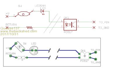
Just give this a try. led is optional.
No real current flows till switch is active.
Page 3 of 4
Print this page
The Back Shed's forum code is written, and hosted, in Australia.