
|
|
Forum Index : Microcontroller and PC projects : Micromite LCD BackPack V2 Display Issue
| Author | Message | ||||
Azure Guru Joined: 09/11/2017 Location: AustraliaPosts: 446 |
Good news, Loup has agreed to send it to me next week. Will keep the thread posted on updates. @WW I will try and find the correct part number or see if I can locate a single transistor screen (still not sure if I have one, good or faulty). |
||||
Quazee137 Guru Joined: 07/08/2016 Location: United StatesPosts: 603 |
Just looked at the ones I have here are the one transistor type with a few different numbers. V2QG V2OD V2PF 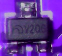 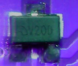 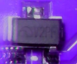 here is a starting point http://www.s-manuals.com/smd couldn't upload so google smd-codebook.pdf |
||||
| Azure Guru Joined: 09/11/2017 Location: AustraliaPosts: 446 |
Below is a text summary of the journey I went on to try and find out why this panel was not working. It has taken a while but I have finally gotten around to seeing what is going on with the faulty module. Took a little bench tidying in amongst other work and lifes issues to be able to really work on it. If you do want to know but don't want to go on the journey, skip to last paragraph. On this LCD Panel that has a "single transistor" it turns out that the transistor is a 3v0 LDO regulator. I powered the whole thing up on the lab supply with the current limited in the 10's of mA as I ramped up the voltage to 5V it quickly hit any current limit I set (up to a few 100 mA's). No magic smoke appeared (still current limited) and no parts getting hot. Resistance check on the LDO input and output to ground and there was only 1 ohm between ground and the LDO output. This went to 2 caps, touch controller IC, SD Card slot and LCD. Removed the LDO (L1), still shorted, removed the Touch controller (U1), still shorted, removed the caps (C1 & C2), still shorted, removed the LCD Panel, short gone. As it turns out the LCD Panel is faulty in more ways than one. On inspection the FPC cable is fractured in several places, this was causing several traces to open or short. On cleaning and patching it as best I could the short between Vcc and ground were now gone. I metered the LDO and caps and they were not shorted. So I reassembled in steps to see if anything was still working. LDO and Caps, Voltage OK, Touch controller, Voltage OK. LCD Panel, Voltage OK on a power only test. The soldering of the fracture in the FPC was not a reliable fix. Also The sheet that pushes the backlight diffuser to the glass has a bump in it, causing it to not properly press against the glass and backlight the actual LCD for illumination. The Backlight has resistor R6 on the PCB which is OK, but the LED's are drawing too much current and way to bright, the light is not dispersed across the screen evenly. I suspect the LED's are faulty and if left running would soon burn out. Knowing I would hopefully not damage my MM BP, I connected it to my MM BP. I used the PWM at 10% to limit the LED brightness, but alas no image. While playing around trying to see if I could fix the LCD fpc and take a closer look at the backlight I noticed with the LCD backlight layers were not sandwiched properly together. There was a dimple in one of the layers preventing it from making proper even contact with the diffuser layer. After carefully dismantling the layers I did the best I cold to try and smooth the dimple out and put it back together. On power in it was still not creating an even fill and overlit at the LED edge. While trying to see if it works with the diffuser pressed to the glass I managed to crack the edge of the glass, so ends the journey. I suspect in all the playing before me and by me as well the fractured fpc connector if nothing else so it cannot reliably pass the data to the COG (chip on glass). Not willing to give up on the search for what WAS originally wrong with this unit, I carefully dismantled the LCD Backlight layers. On close inspection of the LCD Bar the LEDs have spot burns on them. This is the original fault, possibly too much voltage/current applied to the LED power pin have resulted in the spot burning of the LED's and from then on is was all downhill. I'll post some pics in case your interested. |
||||
| Azure Guru Joined: 09/11/2017 Location: AustraliaPosts: 446 |
Parts removed, sitting on PCB, ready to go back in (PCB not cleaned up yet). 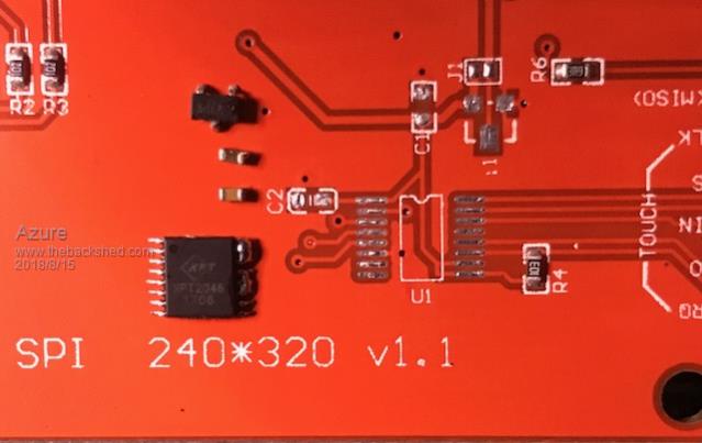 Back of PCB with LCD removed (PCB not cleaned up yet). 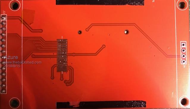 LCD fpc, if you look closely you can see the fractures along the top of the solder pads. 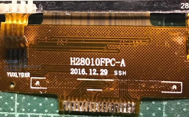 LED Bar, There are 4 thin rectangular LED's, if you look closely you can see a little black burn spot on each one. this is what prevented it from backlighting the Glass evenly.  |
||||
| Azure Guru Joined: 09/11/2017 Location: AustraliaPosts: 446 |
Not a comment from anyone  I thought Grogster, Whitewizzard, Quazee or loup would have a comment. |
||||
| WhiteWizzard Guru Joined: 05/04/2013 Location: United KingdomPosts: 2991 |
Hi Azure, Impressive patience in trying to identify the issue.  This has me thinking. I have seen a massive variation in image quality from these screens. By this, I mainly refer to viewing angle, and brightness (along with evenness of brightness). So I wonder if it is possible to find a 'reliable' manufacturer of a quality panel (and backlight) which has an identical FPC connector. And then attach it to one of 'these' ILI PCBs (after removing the poor quality screen). Although this would be a bit of work, it would be worth it IF a 'quality' screen exists. Once again, great work - and a great write-up. WW |
||||
| Azure Guru Joined: 09/11/2017 Location: AustraliaPosts: 446 |
Thanks WW. In my recent searching I have learned that most (I won't say all because then I will be wrong) of the panels with the same number of pins on the FPC are mostly wired the same. There is quite a variety of fpc with different pin counts. So make sure to first get the correct number of pins then check the pinout. While searching for a decent panel I noticed that 2.8" has become a bit pricy compared to both smaller (2.2" and 2.4") and larger panels (3.2" and 3.5"). What I also found interesting was the single transistor type display was actually a 3.0v LDO (for the controller not LED backlight). |
||||
| Quazee137 Guru Joined: 07/08/2016 Location: United StatesPosts: 603 |
So its a vreg and not a transistor. I got mine in two batch buys well 3 if I count the 2.4's I first got. In the last batch one had a cracked in the touch glass. I took a look and here is the pictures. 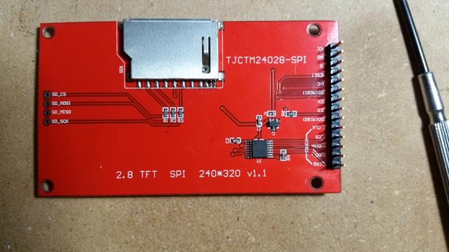 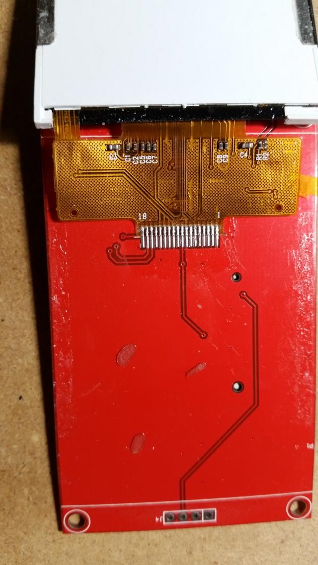 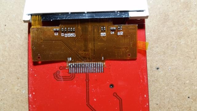 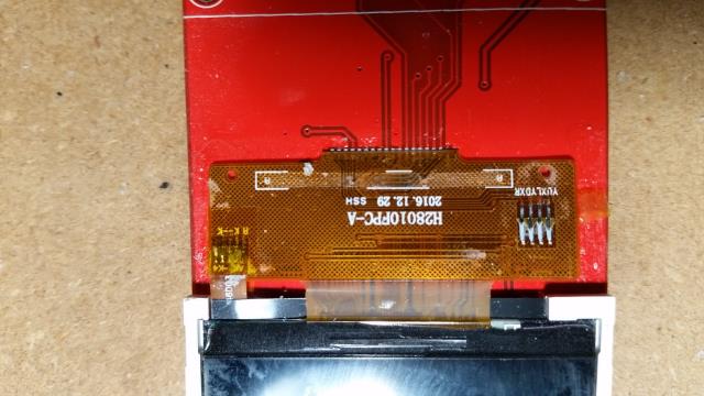 This one same text "2.8 TFF SPI 240*320 v1.1" but has vreg U1 and transistor Q1. 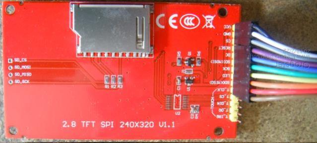 One thing I have noticed is if using a pot to set brightness these run cool. When using pwm they run some what hot. And checking it is R6 that is heating up. Using J1 would by pass the vreg. I wounder if you can run them at lower voltages. The parts layout of the 2.4" and 2.8" look the same with same part labels. Could lay the 2.4 over the 2.8 and they match up. The part numbers for each version is TJCTM24024-SPI and TJCTM24028-SPI. On the ones I have there are 4 different numbers for the vreg's A few months ago I got 1117-3.3 and 1117-5.0 from DigiKey a little miffed to find they had odd house numbers not easy to know right a way what part I have. |
||||
Grogster Admin Group Joined: 31/12/2012 Location: New ZealandPosts: 9975 |
Sorry, did not follow this thread before now.  Reading....... EDIT: Yes, I see the issue you were having with the hairline cracks on the FPC to the PCB. I HAVE seen this before, but my attempts to fix it totally destroyed it, so I decided at that point, to just outright replace. The SPI LCD's are cheap, so..... Smoke makes things work. When the smoke gets out, it stops! |
||||
| Azure Guru Joined: 09/11/2017 Location: AustraliaPosts: 446 |
I have both types of panels (with one or two devices). On the vreg only panel it is definitely an LDO 3.0v. This is power for the COG ILI9341 and touch controller XPT2046. Voltages for these are: XPT2046 2.2v to 3.6v ILI9341 2.5v to 3.3v J1 does short out the vreg so you can connect a low voltage directly into the Vcc pin. But accidentally connecting anything over 3.3v could destroy the panel (since the 5v input LDO is bypassed). So you should be able to run them at between 2.5v to 3.3v and be in safe voltage for both. I will trace out the 2 device panel and see what they are for. |
||||
palcal Guru Joined: 12/10/2011 Location: AustraliaPosts: 2039 |
Maybe this thread will help ILI9341 LED Paul. "It is better to be ignorant and ask a stupid question than to be plain Stupid and not ask at all" |
||||
| The Back Shed's forum code is written, and hosted, in Australia. | © JAQ Software 2026 |
