
|
|
Forum Index : Microcontroller and PC projects : How to learn RF remote codes?
| Author | Message | ||||
Grogster Admin Group Joined: 31/12/2012 Location: New ZealandPosts: 9982 |
Yes, from what I could see, the very first data packet was corrupted. But the subsequent ones were not. I'm glad it makes sense to you!  Smoke makes things work. When the smoke gets out, it stops! |
||||
disco4now Guru Joined: 18/12/2014 Location: AustraliaPosts: 1130 |
Hi Jim, Thanks for this clever idea/tip. I have used it to decode a remote temperature/humidity sensor from Bangood . It was in the too hard basket but this gave me inspiration and I have cracked the decoding of it. I will start another thread about it so as not to hijack Grogster's thread any further. thanks Gerry F4 H7FotSF4xGT |
||||
TassyJim Guru Joined: 07/08/2011 Location: AustraliaPosts: 6541 |
Grogster, Can you try this code generator and see if it matches your devices. It runs on a MX170 with the Tx pin on pin 16 but can be any. enter 0 to 9 to select the code you want to send. All codes are the same in this demo except No 9 which has an "N" as the first digit. This cause a burst of random noise to be sent before the data. The pulse length is set at 295uS which might need tweaking. Long pulses are 3 times the short ones. Thanks to PeterM and disco4now for the code I based it on. If it looks OK, I will start playing with receiving the data. Jim VK7JH MMedit |
||||
| Grogster Admin Group Joined: 31/12/2012 Location: New ZealandPosts: 9982 |
Hi Jim.  Thanks very much for your efforts!  Do you want me to capture the output of your code from the 170, into the logic analyser and compare with the actual transmitter? I think that is what you want me to do, yes? EDIT: I can't feed it into the TX and then receive on the receiver, as the Tx units are sealed watches, and unless you want me to hack one of those to bypass the 1527, and inject the data to the TX side of the device and then receive THAT across the link.... I can put up a photo of the internals of the watch TX if you like, but it is just a small PCB with the TX AND encoder all on one, along with the button and batteries. Smoke makes things work. When the smoke gets out, it stops! |
||||
| TassyJim Guru Joined: 07/08/2011 Location: AustraliaPosts: 6541 |
Just feed the output directly into your logic analyser and compare. I am looking for a way of testing various receive decoding methods without having the transmitter or receiver. Jim VK7JH MMedit |
||||
| Grogster Admin Group Joined: 31/12/2012 Location: New ZealandPosts: 9982 |
Hi there. @ TassyJim - Here is the data you requested. I have run tests 1 and 9. If you need more tests, please let me know. 2018-03-17_163102_TassyJim_01tests_1_and_9.zip Smoke makes things work. When the smoke gets out, it stops! |
||||
| TassyJim Guru Joined: 07/08/2011 Location: AustraliaPosts: 6541 |
That looks good enough to play with. Jim VK7JH MMedit |
||||
| Grogster Admin Group Joined: 31/12/2012 Location: New ZealandPosts: 9982 |
Awesome. Do you want me to do any of the other tests? (2-8) Smoke makes things work. When the smoke gets out, it stops! |
||||
| TassyJim Guru Joined: 07/08/2011 Location: AustraliaPosts: 6541 |
When I 'sent' this "011101010001110000000010" I received and decoded this "001110101000111000000001000111010100011100000000100011101010001110000000010" Which is the sent code repeated 3 times. The extra zeros are the sync pulses. The sender is a 170 and the receiver is an explore64. The receiving code is basically the one I posted earlier in the discussion. I need to sort out the sync pulse timing and try some other, faster methods of decoding to get it running on an 170 although I assume you have a few spare explore64s available. By using the simulator instead of the real thing, I can push the speeds up to see how close we are to failure. Jim VK7JH MMedit |
||||
| Grogster Admin Group Joined: 31/12/2012 Location: New ZealandPosts: 9982 |
Marvellous, thanks for your efforts. Yes, I have E64's here if I need to use one for testing anything you need. Smoke makes things work. When the smoke gets out, it stops! |
||||
| TassyJim Guru Joined: 07/08/2011 Location: AustraliaPosts: 6541 |
How it works. The PWM 1 output is connected to a counting pin with a frequency of 100kHz. That gives us a tick counter of 10uS On the explorer64, PWM is on pin 48 which is conveniently next to count pin 49 I used pin 46 for the radio receiver input but any would do. The interrupt routine attempts to wait for a sync pulse then fills the pulses()array with the time intervals. It is limited to 400 ticks so we don't overflow our string when it comes to decoding. After 400 ticks, it loops from the start. There is a SETTICK timer which periodically checks the pulses() array and looks for patterns it recognises. It is set to 3 seconds for testing but should be as often as possible once the debug printing is removed. I would try 500mS to start with. There is a timer to keep track of time taken to decode to enable setting the best decode interval. The decode SUB scans the array and looks for sync pulses. It also compares two adjacent time intervals and decides if we have a "1" or "0" The results are stored in a string. The string is then scanned for each of the "residents codes" and if found, raises an alarm. If the receiver doesn't have a squelch, the code will spend a lot of time in the interrupt SUB. The main thing to check is the different times saved for 'short' and 'long' pulses If the times are too close together, we have reached to limits of the micromite. In the above example I sent two codes quickly and both were found in the one string. You need to fill the array with some valid codes. 2018-03-18_152629_panicalarm.zip I have attached this file for the exp64 and an updated sending file for the MX170 with the device codes set to match sender and receiver. code 9 still send code 1 with noise at the start. Clear as mud? Jim VK7JH MMedit |
||||
| Grogster Admin Group Joined: 31/12/2012 Location: New ZealandPosts: 9982 |
AWESOME! Thank you VERY much for your efforts. I will load this into an E64 tomorrow. I wish I could tonight, but I don't have time.  With the array storing the remote addresses, that will work beautifully. If I wanted to LEARN a new remote code into the system, is there much involved in that kind of idea? I know this is not part of your demo code, and I may well be able to work it out from the sample code you have supplied...... Smoke makes things work. When the smoke gets out, it stops! |
||||
| TassyJim Guru Joined: 07/08/2011 Location: AustraliaPosts: 6541 |
To learn a new code, run it with PRINT code$ active. That will give you a line similar to the example output. Copy the data between two 's' markers and paste it into the array section of the program. If you have a good decode, there will be three the same in the string. In practice, checking the string every 500mS or more often is required to prevent overwriting good data with noise. This means you are likely to get half a code in most strings but with three being sent, there should always be at least one good one. It could be automated without too much effort but lets see how well it works in real life first. Jim VK7JH MMedit |
||||
| vegipete Guru Joined: 29/01/2013 Location: CanadaPosts: 1181 |
To add to the confusion, looking at Grogster's screen shot, and later link to the wider screen image, the valid data starts just before about the 30ms mark. The long low pulse is the inter-packet delay. My original decoding firmware always missed the first packet because the noise was being interpreted as valid pulses that weren't cleaned up until a long low appeared. Before changing to a better receiver, my software plan was to pay more attention to pulse lengths. Pulses representing zero and one bits have fairly specific lengths, although this jitters a bit because there is no synchronization between transmitter and receiving software. My plan was to reset the incoming pulse count any time the pulse was shorter than the shortest valid pulse or longer than the longest one. How much shorter or longer? Well, I never got around to actually trying different values because of the change in hardware. This firmware was to be running in C or assembly on the target microcontroller. I have no idea if interpreted MMBasic is fast enough to catch these subtle variations in pulse length. Using hardware with a radio signal strength indicator really simplified things. Visit Vegipete's *Mite Library for cool programs. |
||||
| Grogster Admin Group Joined: 31/12/2012 Location: New ZealandPosts: 9982 |
Finally had a chance to play with this. Sorry for the delay. It appears to be working with my test transmitter unit: (E64 1C, MMBASIC 5.04.08, default speed(100MHz))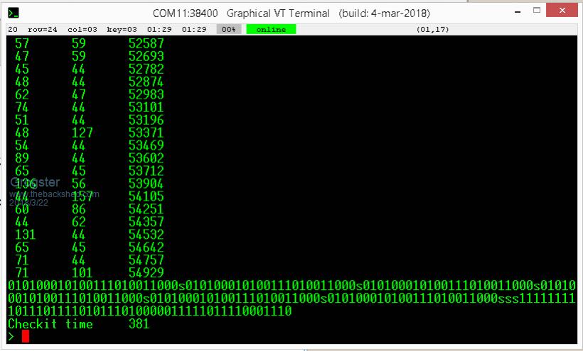 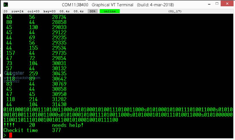 First image is just me running the code, 2nd image is with me putting the transmitter code into slot #20, which then does respond. So, this is the first actual test with the actual transmitter and not just with a simulator, but they seem to agree. Anything else you would like me to try? Smoke makes things work. When the smoke gets out, it stops! |
||||
Azure Guru Joined: 09/11/2017 Location: AustraliaPosts: 446 |
If it's not too long can you post the current code being used. My only suggestion is it needs a valid sync detected before it attempts to decode. That way it wont try to decode the noise. |
||||
| Grogster Admin Group Joined: 31/12/2012 Location: New ZealandPosts: 9982 |
Go back to the end of page 6. It's a direct copy of the code Jim posted for me to try. Smoke makes things work. When the smoke gets out, it stops! |
||||
| TassyJim Guru Joined: 07/08/2011 Location: AustraliaPosts: 6541 |
That is very promising. It shows that my timing was close to the real thing. The next big thing is to get access to the WAKEB pin on the IC and use it as an interrupt to configure the main data interrupt. I would set the data interrupt ON when you have RF and OFF when it stops. That should prevent any overwriting. Jim VK7JH MMedit |
||||
| Grogster Admin Group Joined: 31/12/2012 Location: New ZealandPosts: 9982 |
Cool, I will try that next. I should configure the interrupt pin(from WAKEB) to fire the BLIP sub, yes? Smoke makes things work. When the smoke gets out, it stops! |
||||
| TassyJim Guru Joined: 07/08/2011 Location: AustraliaPosts: 6541 |
THis is how I would try: rem out the original "SETPIN rxPin, INTB, blip" The interrupt to blip is only active when there is likely data arriving. It is not called at all when there is no RF. Jim VK7JH MMedit |
||||
| The Back Shed's forum code is written, and hosted, in Australia. | © JAQ Software 2026 |
