
|
|
Forum Index : Microcontroller and PC projects : Armmite L4 battery miser, first beta
| Author | Message | ||||
OA47 Guru Joined: 11/04/2012 Location: AustraliaPosts: 1050 |
Peter, just to report in, the 5110 display running on the L4. Works a lot better when you re-read your post and realise it is supported on the 2nd port. 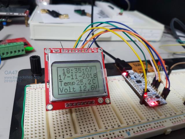 I didn't disconnect the LED on the CLK pin 26 and was wondering if you thought it would hinder the operation? OA47 |
||||
| matherp Guru Joined: 11/12/2012 Location: United KingdomPosts: 11515 |
Forgot to mention in the last update. For all the mono displays you can write to them as required. Then, if you want to power them off to save battery, when power is re-applied just use the command GUI RESET LCDPANEL and the display will be reset WITH the previous contents restored. Thanks for the report. Should be fixed in this release, would affect all mono displays. 2018-11-17_203330_ArmmiteL4.zip Sorry - should have been clearer - all displays use SPI2, the LED doesn't seem to cause a problem Haven't made any changes that could affect this - wouldn't know how. Please try both the hex and bin in the attached using ST-LINK and/or mbed and see if there are any differences Don't understand this as the correct code is in the source. I've got a display on order so will diagnose further when it arrives I2C_Send_Command(0xAE);//DISPLAYOFF I2C_Send_Command(0xD5);//DISPLAYCLOCKDIV I2C_Send_Command(0x80);//the suggested ratio &H80 I2C_Send_Command(0xA8);//MULTIPLEX if(Option.DISPLAY_TYPE==SSD1306I2C)I2C_Send_Command(0x3F); else if(Option.DISPLAY_TYPE==SSD1306I2C32)I2C_Send_Command(0x1F); I2C_Send_Command(0xD3);//DISPLAYOFFSET I2C_Send_Command(0x0);//no offset I2C_Send_Command(0x40);//STARTLINE I2C_Send_Command(0x8D);//CHARGEPUMP I2C_Send_Command(0x14); I2C_Send_Command(0x20);//MEMORYMODE I2C_Send_Command(0x00);//&H0 act like ks0108 I2C_Send_Command(0xA1);//SEGREMAP OR 1 I2C_Send_Command(0xC8);//COMSCANDEC I2C_Send_Command(0xDA);//COMPINS if(Option.DISPLAY_TYPE==SSD1306I2C)I2C_Send_Command(0x12); else if(Option.DISPLAY_TYPE==SSD1306I2C32)I2C_Send_Command(0x02); I2C_Send_Command(0x81);//SETCONTRAST I2C_Send_Command(0xCF); I2C_Send_Command(0xd9);//SETPRECHARGE I2C_Send_Command(0xF1); I2C_Send_Command(0xDB);//VCOMDETECT I2C_Send_Command(0x40); I2C_Send_Command(0xA4);//DISPLAYALLON_RESUME I2C_Send_Command(0xA6);//NORMALDISPLAY I2C_Send_Command(0xAF);//DISPLAYON |
||||
| Frank N. Furter Guru Joined: 28/05/2012 Location: GermanyPosts: 1102 |
Hi OA47, would you share your 5110 display code (and pin assignment)? THANKS! Frank |
||||
disco4now Guru Joined: 18/12/2014 Location: AustraliaPosts: 1127 |
Hi Peter, The option list for LCDPANEL SSD1306I2C32 shows a couple of extra characters. Could these be causing the code not to match the if(Option.DISPLAY_TYPE==SSD1306I2C32) condition.(They are not ## but something shows up. Did not show in the post so I added ## to show where they appear) option list OPTION LCDPANEL SSD1306I2C32##, LANDSCAPE > Regards Gerry F4 H7FotSF4xGT |
||||
| matherp Guru Joined: 11/12/2012 Location: United KingdomPosts: 11515 |
Well spotted  Corrected here: Corrected here:2018-11-17_231911_ArmmiteL4.zip My display just arrived and works with this release  |
||||
| lizby Guru Joined: 17/05/2016 Location: United StatesPosts: 3784 |
Doh! Thanks. Now, what's the best low-real-estate way to keep the RTC going if you are plugging in and removing the USB cable? A coin cell (CR2032) and a diode to the power rail? Sometimes I've had to power-cycle to regain the MMBasic prompt--Ctrl-C and the reset button didn't do it. Will unplugging USB suffice, or will I need to unplug the CR2032 as well and reset the RTC? PicoMite, Armmite F4, SensorKits, MMBasic Hardware, Games, etc. on FOTS |
||||
| OA47 Guru Joined: 11/04/2012 Location: AustraliaPosts: 1050 |
Frank, I have used OPTION LCDPANEL N5110, L,11,10,9 So my interconnections are Connection L4 5110 MMBASIC SPI_CLK (D13) 7 PIN 26 SPI_OUT (D11) 6 PIN 28 DC (A4) 5 PIN 11 RST (A3) 4 PIN 10 CE (A2) 3 PIN 9 GND GND 2 +3V3 3V3 1 Here is the CODE ' Program to test Nokia 5110 LCD on ARMmite L4 ' Option LCDPanel N5110,L,11,10,9 set on command line SetPin 6,AIN Dim T$, D$, I, Tmp,V CLS Box 0,0,83,48 Do T$=Time$ If T$ <> Time$ Then D$=Date$ V= 12.6 'Pin(6)/11.1 'resistor divider between Vin and GND Tmp=25.4 'TEMPR(22) Text 10,1,T$ Text 2,12,D$ Text 3,23,"Temp" Text 36,23,Str$(Tmp) Text 70,23,"C" Text 3,34,"Volt" Text 41,34,Str$(V) Text 72,34,"V" End If Loop And if any of the Aussie shedders need a 5110 display quickly, Jaycar stocks them as: XC4616 64X48 DOT MATRIX @ $19.95 |
||||
| disco4now Guru Joined: 18/12/2014 Location: AustraliaPosts: 1127 |
I still have a little mystery with mine. OPTION LIST displays OK and the fix for attempted printing for x<0 is good. I could not get it to work without fixme. It turned out I only needed the I2C OPEN 400,1000 line so the rest of setup is good.It seems like the SSD3306 driver will use I2C as is, if already open. I was not using any pullups, so added 10K to 3.3v. This seemed to not make any difference,the driver does not work unless I open the I2C first. What speed is the driver opening the I2C bus, what value pullups, if any, do you have? Regards Gerry F4 H7FotSF4xGT |
||||
| matherp Guru Joined: 11/12/2012 Location: United KingdomPosts: 11515 |
One more try.  2018-11-18_184313_ArmmiteL4.zip 400K, none - the chip applies internal pullups |
||||
| disco4now Guru Joined: 18/12/2014 Location: AustraliaPosts: 1127 |
Yes that has got it now! Thank you. F4 H7FotSF4xGT |
||||
| Frank N. Furter Guru Joined: 28/05/2012 Location: GermanyPosts: 1102 |
@OA47: Thank you very much for your code and infos! I will try it! Frank |
||||
| OA47 Guru Joined: 11/04/2012 Location: AustraliaPosts: 1050 |
No problem Frank. Here is the code with the DS18B20 and the real Vin. ' File L4TEST.V10 ' Program to test Nokia 5110 LCD on ARMmite L4 ' Option LCDPanel N5110,L,11,10,9 set on command line SetPin 13,AIN 'Voltage reading of Vin SetPin 29,DOUT 'Supply 3V3 to DS18B20 Pin(29)=1 Dim T$, D$, I, Tmp, V CLS Box 0,0,83,48 Do If T$ <> Time$ Then T$=Time$ D$=Date$ V= Pin(13)*11.0 'resistor divider 100K/10K between Vin and GND Tmp=TEMPR(22) Text 10,1,T$ Text 2,12,D$ Text 3,23,"Temp" Text 37,23,Str$(Tmp) Text 70,23,"C" Text 3,34,"Volt" If V > 10.0 Then Text 41,34,Str$(V,2,1) Else Text 41,34,Str$(V,1,2) End If Text 72,34,"V" End If Loop OA47 |
||||
| viscomjim Guru Joined: 08/01/2014 Location: United StatesPosts: 925 |
Just received my nucleo board. Downloaded matherp's zip file, un-zipped it, plugged board into a USB port, copied .bin file to board, fired up mmedit, scanned for port, connected, up and running. This has got to be the easiest method I've ever encountered. Great work!!! Now the ultra low current fun begins.... I guess I won't have to buy too many batteries now.... A truly gigantic thanks to Peter for the port and Geoff for MMbasic. This is just fantastic! At about $11 bucks a board, I can see a few of these things in the wild, on batteries, for quite a while. |
||||
TassyJim Guru Joined: 07/08/2011 Location: AustraliaPosts: 6538 |
They are a nice board. I am having trouble working out what happens when you try and run 'unattached' I have SB9 open so the CPU runs when the ST-link is powered down. I am feeding the CPU with a 3.3V supply through JP1 and the internal regulator shut down. With the USB plugged in, running my test program which spends most of the time in PAUSE, it draws 0.6mA. When I unplug the USB, the current increases to 2.2mA when using an older firmware and 2.8mA using the current firmware. I can measure ~2V on the supply to the ST-Link so I can only assume that we are getting some feed back through some of the signal lines that link the two CPUs. There are solder bridges on some of the lines but not all. The other problem is with the newer firmware. A reset will not restart the program with the USB unplugged. It does restart correctly with the USB plugged in. If you have to keep the ST-Link powered up, it will make a mess of the power saving efforts. Jim VK7JH MMedit |
||||
| OA47 Guru Joined: 11/04/2012 Location: AustraliaPosts: 1050 |
As I intend to battery power this project, I thought the display needed a battery bar-graph. I can post the code snippet if anyone is interested. 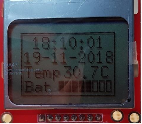 OA47 |
||||
| matherp Guru Joined: 11/12/2012 Location: United KingdomPosts: 11515 |
Jim Can you try the attached and see if it makes a difference to booting with no USB 2018-11-19_184216_ArmmiteL4.zip The only difference is that I have re-disabled access to the SWDIO and SWCLK pins from within MMBasic. All, please note there was a bug in previous versions that corrupted the MEMORY command after using EDIT. This version also fixes that. In general, I do not expect the Nucleo to be the basis for real projects. I've got some STM32L432 chips and UFQFPN32 breakouts on order to play with but the final "project" PCB may well use the 48-pin STM32L431 which is easier to solder. The same binary will be able to work on both chips and by maintaining the An, Dn, pin naming code should be portable with zero changes. PS Making progress with a file system on flash memory - google "LittleFS" for info. |
||||
| Frank N. Furter Guru Joined: 28/05/2012 Location: GermanyPosts: 1102 |
@OA47: I'd be very interested in your code! CAN ANYBODY HELP ME WITH MY 5110? My 5110 worked very well at the beginning - after a while the display turned into a black field!  Is there a way to adjust the contrast using the code? Frank |
||||
| matherp Guru Joined: 11/12/2012 Location: United KingdomPosts: 11515 |
Page 3 of this thread Option LCDpanel N5110, orientation, CDpin, RSTpin, CEpin [,contrast] 'Try contrast values between &HA8 and &HD0 to suit your display, default if omitted &HB1 |
||||
| Frank N. Furter Guru Joined: 28/05/2012 Location: GermanyPosts: 1102 |
Thank you, Peter, I've overlooked that. Now it works again!  Frank |
||||
| lizby Guru Joined: 17/05/2016 Location: United StatesPosts: 3784 |
Yay for littleFS. If need be, I would be willing to give up 10K of basic program space for a file system. Amazing that it reduces the code needed for FATFS by more than 50%--with additional failsafe features. Also yay for a 48-pinner. Thanks for your work on this great addition to the MMBasic family. PicoMite, Armmite F4, SensorKits, MMBasic Hardware, Games, etc. on FOTS |
||||
| The Back Shed's forum code is written, and hosted, in Australia. | © JAQ Software 2026 |
