
|
|
Forum Index : Microcontroller and PC projects : CMM2 - Maximite2 Kit v3.0 PCB build notes
| Author | Message | ||||
| Womble Senior Member Joined: 09/07/2020 Location: United KingdomPosts: 267 |
Here is what I get, the numbers look to be OK: 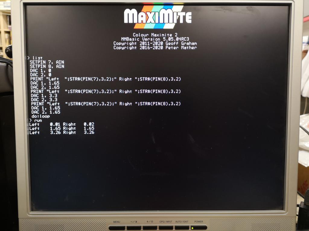 TJ_PetersFFTdemo_pin78.zip The hookup I used. Tip to pin#7, Ring to pin#8, Sleeve (GND) pin#9 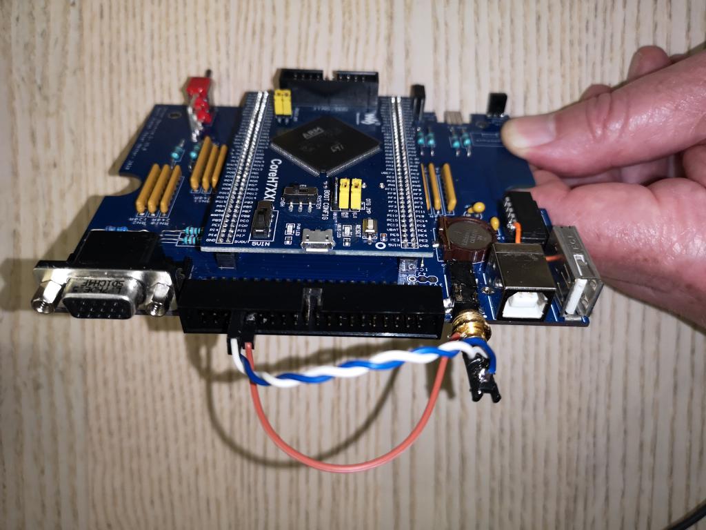 My results file: 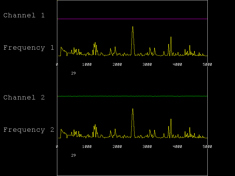 I can see the noise on Channel2. Definitely something is not right. I did try running the FFT_Demo with the audio cable plugged in in place of the harness connecting to pin7 & pin8 (and ground) and Channel1 and Channel2 both showed the same noise output. As you can see I have removed the motherboard from the case when carrying out this test (using the original Waveshare, as I am scared of damaging my new one). Given the comments regarding the 80pin headers, I checked all the connetions again, and touched each pin with a hot iron to reflow them in case there was a bad joint. I did this before carrying out the above test, and it made no difference  Many thanks for your assistance everyone, it is very much appreciated. |
||||
| Womble Senior Member Joined: 09/07/2020 Location: United KingdomPosts: 267 |
I agree, actually I have been unplugging the audio completely. Unfortunately when I do, the keyboard freezes seem to happen more frequently. I was concerned enough that I was damaging the device by using it that I had halted all work, pending new Waveshare (which didn't fix the problem) and further advice from the community. I have also contacted Phil (WW) at Micromite who suppplied the kit for his comments. In case the eagle eyed amongst you have spotted this: 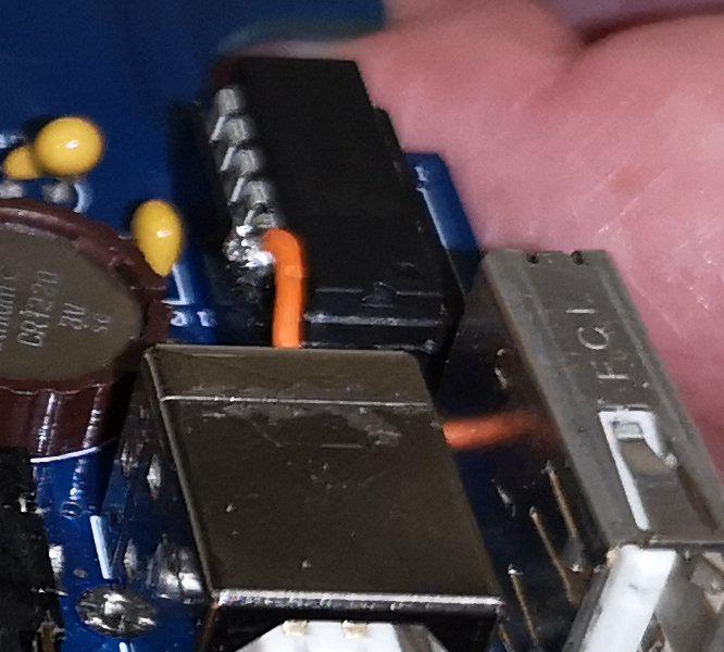 I had a problem with the MCP221A socket. Duff pin. So soldered a bodge wire direct from there to the appropriate pin on the USB-B connector. Next time I will use a turned pin socket as these seem to be better quality. Mea Culpa |
||||
TassyJim Guru Joined: 07/08/2011 Location: AustraliaPosts: 6538 |
I wouldn't be too concerned with the slight ripply in the second channel audio. The re is a similar, but not as much, ripple in my upper channel and I put that down to quantizing error. You did say you have noise on both channels and the upper trace is dead flat. The strength of the frequency buckets is the same as mine so I can't see any reason for your noise. Does it look the same without the ground wire connected between the audio plug and the IO connector. If you have trouble with the keyboard with the audio unplugged, I would be looking closely at the 5V and ground connections on both USB sockets. The ground for the audio socket is connected to one of the mounting posts of the USB power socket. The fill areas on the upper side of the board are 3.3V, while the fill areas on the lower side are ground. Jim VK7JH MMedit |
||||
| Womble Senior Member Joined: 09/07/2020 Location: United KingdomPosts: 267 |
Yes  Yes Thanks Jim, your comments are very helpful. I have metered out the connections to/from the USB connectors, and all appear good. There is a very good connection between the Audio Ground connection on the socket and the USB power socket case/mounting post. I have also carefully examined the connections for the USB A & B sockets, and they look really good, even the one I linked with my "bodge wire" 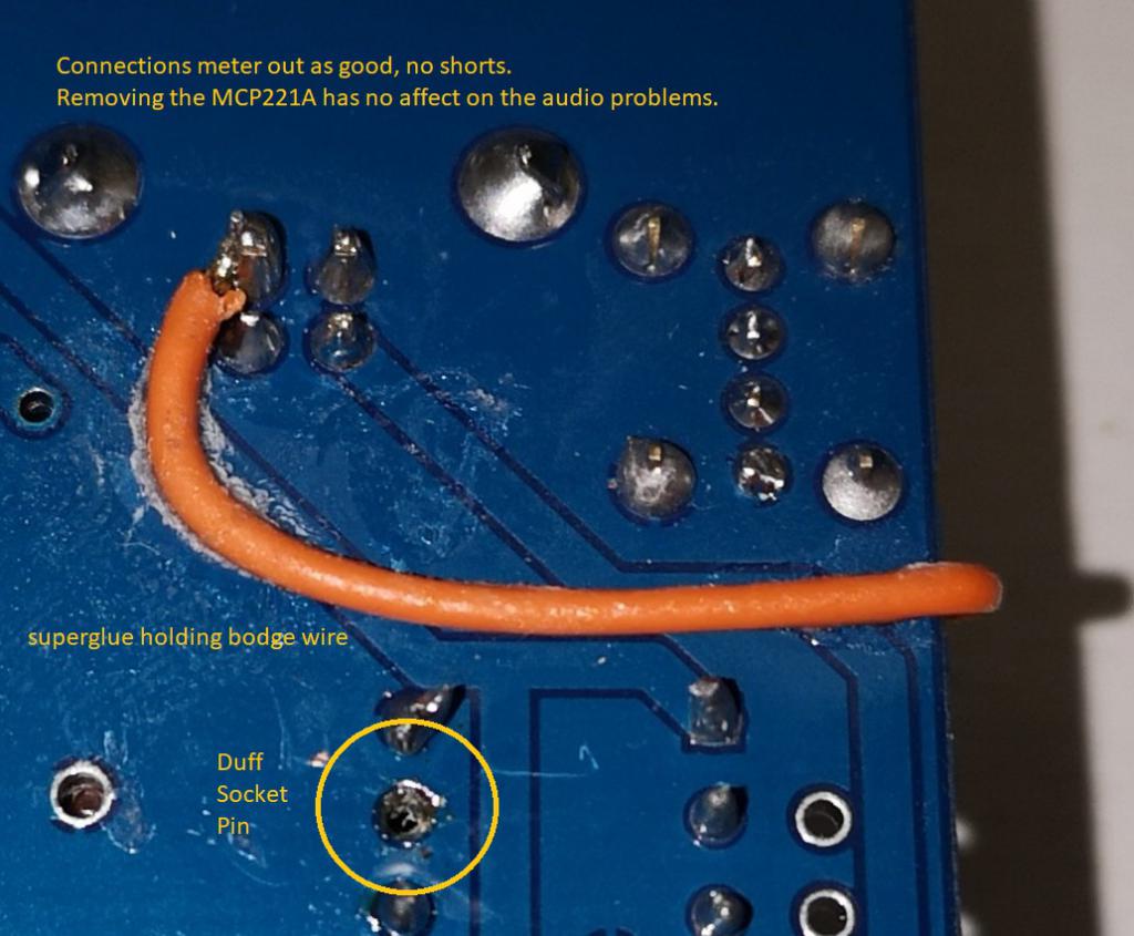 Not the prettyest soldering, but not dreadful, apart from the socket bodge cock-up Mea Culpa |
||||
| TassyJim Guru Joined: 07/08/2011 Location: AustraliaPosts: 6538 |
In the code I posted earlier, remove the comments from play tone 1000,2000 play volume 30,30 and try different VOLUME levels. What is the relative level of the noise compared to the tones? You should be able to find a level where the noise and the tone are roughly equal. Jim VK7JH MMedit |
||||
bigmik Guru Joined: 20/06/2011 Location: AustraliaPosts: 2981 |
Hi Womble, I am sorry if my suggestions have already been tried but here are what I would look at first 1. GND connection to the 3.5mm stereo jack test it with a connector plugged in as the socket itself may be faulty. ie test the pins on the male that plug into the socket not just on the PCB. 2. Power the CMM2 off a battery bank, like used for mobile phones, this removes any possibility of mains hum or noisy PC power etc 3. Test the 5Volt supply you are getting on the CMM2 (maybe at the Voltage regulator) 3a. Test the 3.3 Volt power supply the regulator gives 3b. Test the current the CMM2 is drawing (use one of those cheap USB power testers) 4. Carefully follow the copper traces from the audio left and right channels and make sure there is no solder splash or other `crud' shorting out adjacent pins These go to the CPU pins 50 and 51, I would look at the point where the 2mm header is soldered onto the PCB (check both sides some grease or other may have plopped there somehow. 5. work around: Get 2 1uf-4k7uf electrolytic or other capacitors (for each channel) and solder the 2 negative legs together, this will give you effectively a bipolar capacitor (of half the selected value) solder them in series with each channel going to the amplifyer. I would be quite happy to look at it for you but being on the opposite side of the world makes this not only expensive but will take a fair bit of time with 2 way shipping. Kind Regards Mick Edited 2020-08-06 16:27 by bigmik Mick's uMite Stuff can be found >>> HERE (Kindly hosted by Dontronics) <<< |
||||
| Womble Senior Member Joined: 09/07/2020 Location: United KingdomPosts: 267 |
No problem, I'm open to suggestions. It does not hurt to double check. Checked that, both with, and without a cable pulged in, meters OK Tried with multiple power supplies, and a USB Battery Power Bank. Same results. Tested as per the "Construction Manual, Fault Finding on page 4" = 152ma with Waveshare & firmware Measured voltages at 40Pin IO connector (the regulator is inaccessible on bottom of Waveshare) 3.3v rail = 2.81v measured 5v rail = 3.94v measured Same voltages were measured between the USB-B CASE and the 5VIN & 5VOUT pins (3.94v) and 3.3V pins (2.81v) on the Waveshare For the purposes of these measurements I was using a USB Power Bank/Battery which measures at 5.17v unloaded. Using my "Normal" Lenovo USB Power Supply, which measures 5.44v unloaded. 3.3v rail = 3.3v measured at the Waveshare pins 5v rail = 4.49v measured at the Waveshare pins I carefully cleanead any flux residue using "flux cleaner" and a toothbrush to make sure the board was clean. I have been over the solder joints with a jewellers loupe, and also got a friend to check the joints in case I missed anything ... I cannot see a problem, maybe thats just my inexperience. I have examined the traces from PA4 and PA5 (CPU pins 50 & 51) which carry the audio to the socket. All look good. One thing I did notice. Are you supposed to see light through the VIA's on the PCB ? When I hold the board up to the light, I can see thhrough some of them, and examine them closely with my magnifying glass. Others seem to be bunged up with flux. I have cleaned the board, but did not want to poke at these in case I made things worse. Not tried this ... yet! I did try an audio ground loop isolator in the cable to my amplified speakers. Made absolutely no difference. Mick, Your offer to take a look is most appreciated, however in view of the distance involved, probably not a good idea. I have been in touch with Phil (WW) from whom I purchased the kit. He has my phone number, and will likely be in touch as soon as his busy schedule allows. Many thanks for your kind help. Womble |
||||
| robert.rozee Guru Joined: 31/12/2012 Location: New ZealandPosts: 2528 |
that is way too low! the AMS1117 regulator used on the waveshare module requires 1 volt of headroom, so to regulate the 3v3 correctly would require at least 4.3v input. i have a suspicion you may find the 5v supply going into the waveshare module is dropping volts somewhere. try connecting your multimeter between the 5v input pin on the USB console connector and the 5v input pin on the waveshare module. observe any drop between these points when running a program that causes noise on the speakers. if you see no drop, try connecting your multimeter between the ground pin on the USB connector and one of the ground pins on the waveshare module, and see if there is any voltage drop there. an analog multimeter is best for these sorts of tests, as the needle will respond far quicker than a DMM can. even better is an oscilloscope with channels A and B set to subtract from each other (so showing the voltage difference between A and B). i once worked on a project where the main supply for a product was accidentally routed through a single tiny track buried within a 12-layer PCB, so these sorts of things do happen. it could also be that it is passing through a single via somewhere that is flaky. vias can be filled with solder if they don't have the silkscreen running over them, this will (in general) increase their current carrying capacity. cheers, rob Ā :-) Edited 2020-08-06 23:26 by robert.rozee |
||||
| Womble Senior Member Joined: 09/07/2020 Location: United KingdomPosts: 267 |
I found those measurements suspicious too. I'm using this Power Bank which I believe has some "smart" voltage sensing electronics (its the only one I posess), its only a couple of weeks old and has a fresh charge in it. however using my normal psu the 3.3v pin on the Waveshare measures OK. And the 5v rail is sitting at 4.49v You may be onto something here. If the 5v rail goes too low that would account for the keyboard stopping responding. Thanks Rob ... I have an analogue meter so I'll give that a go. I wonder if the bunged up vias are full of silkscreen ? We may be getting to the bottom of this one ... Regards Womble |
||||
| TassyJim Guru Joined: 07/08/2011 Location: AustraliaPosts: 6538 |
Don't worry about the vias being full of something. It is probably solder mask and is not a problem in the vias. VK7JH MMedit |
||||
| bigmik Guru Joined: 20/06/2011 Location: AustraliaPosts: 2981 |
Hi Womble, I think we are starting to get to the bottom of things here.. Firstly I only have the All-in-One boards so not the one with the waveshare module... So any suggestions are theories.. It sound to me that there is something seriously wrong with the 5v Input side.. My first guess is you have a filter cap reversed.... Can you post a decent high quality picture of the top of your board so we can see if there is anything obvious there? 142mA draw also seems high, I think that when I measured mine it was in the vicinity of 70mA but I will recheck that and get back to you.. A test, esp the one that shows 3.94v on the 5V ... Can you remove the waveshare and measure this voltage? There is basically nothing that I can think of that would draw more than a few mA with the waveshare removed so the power reading should be more or less the same as an unloaded measurement of your power supply. I dont know what a 5v Lenovo power supply is (I would have thought they were usually around 19v) but maybe it is for a phone etc?? If so then it shouldnÆt drop below 5v and even with that the volts are pretty low.. Regards, Mick **** EDIT OK I measured my current with no keyboard the draw is about 190mA,3 UBS meter thingamajigs ranged from 150, 170 and 199mA so I reverted to putting a meter across the switch and it showed about 193mA.. Note to self Do not buy those KEWEISI USB meters.. The one that reads just a tad high was a Jaycar kit I built that was probably in a silicon chip or similar magazine. Mik Edited 2020-08-07 14:51 by bigmik Mick's uMite Stuff can be found >>> HERE (Kindly hosted by Dontronics) <<< |
||||
| bigmik Guru Joined: 20/06/2011 Location: AustraliaPosts: 2981 |
Hi Womble, All, I have had a look at the images of the Waveshare PCB located in the construction pack and the only two capacitors that could be causing your problem, by being reversed, are located: 1. Immediately below the coin cell +ve towards the Coin cell 2. under the waveshare, more or less in the centre, +ve towards the 2R2 resistor. Both should be 10uf (by looking at the schematic, although the one under the waveshare in the photo is actually a 1uf, however the value isnt critical.. If they are both correct orientation then I would suggest removing both and testing again. Another thing I thought of is to measure the voltage across the switch itself.. maybe it is faulty. Kind Regards Mick Mick's uMite Stuff can be found >>> HERE (Kindly hosted by Dontronics) <<< |
||||
| JohnS Guru Joined: 18/11/2011 Location: United KingdomPosts: 4335 |
I have the mobo+waveshare and can check voltages/current if someone can be exact enough for a dumb programmer to know where I'm probing. (I get how to use a meter etc but don't know exactly where to measure the 5V for example.) My board didn't use anything like 142mA (I have one of those USB plugin things that shows volts and amps) during my usage but it's not driving a keyboard or the like as I just use a Linux terminal program. John Edited 2020-08-07 16:16 by JohnS |
||||
| KeepIS Guru Joined: 13/10/2014 Location: AustraliaPosts: 2175 |
The Waveshare board unit @ 480Mhz draws 242.213 mA. The voltage at the switch should be no less than 4.8v otherwise you have a dud power pack or insufficient power from the USB port if powering from a PC. Although it can run down to 4.3v, there is danger of loosing the active filtering provided by the 3.3v regulator at that point, and from then on the 3v3 supply sags and with more noise on the rail. The 3.3v out should be very close to 3.3v. With 5.07v on the switch there is 5.03v on the 5v pin on the Waveshare board. . . Edited 2020-08-07 17:07 by KeepIS NANO:Inverter V 8.2ks -┬ĀLinux AvrDude GUI script V4.1 |
||||
| robert.rozee Guru Joined: 31/12/2012 Location: New ZealandPosts: 2528 |
i would find even just a 0.04v drop between the USB console connector and the waveshare module to warrant further investigation. i'd also suggest measuring the voltage drop between the 0v pin on the USB console connector and one of the ground pins on the waveshare module. look at the CMM2 PCB and try and trace out the flow of power between the USB console connector and the waveshare module - look closely at any narrow tracks in this circuit, along with any places where the supply lines pass through single vias. ideally, a current of 200mA should be shared between several larger vias in a row, preferably with those vias filled with solder just to be on the safe side. remember: cross-sectional area of a trace is width x copper thickness. for a via, this translates to 3 x hole-diameter x plating-thickness. these can multiply out to surprisingly small numbers. this is why you will often see designs that use exposed vias that are solder-filled, tight groups of vias, and tracks of exposed copper tinned with solder to 'thicken up' power traces. cheers, rob :-) |
||||
| matherp Guru Joined: 11/12/2012 Location: United KingdomPosts: 11499 |
The 5V path is all 50 thou track and only passes through the board twice, once using pads that take the leg of through hole components and the other time using a 56 thou via with a 32 thou hole. This is the same on all variants of the motherboard and all-in-one board |
||||
| Volhout Guru Joined: 05/03/2018 Location: NetherlandsPosts: 5930 |
Be sure to make all voltage measurements with the multimeter minus lead connected to the same pin (i.e. metal shield of the USB connector). I have fallen into a pit once where I suspected the 5V line, but it was a poor ground connection. Another test could be to put your multimeter on AC and check if there is ripple on the 5V (under load - when the CMM2 is ON). Edited 2020-08-08 00:53 by Volhout PicomiteVGA PETSCII ROBOTS |
||||
| Womble Senior Member Joined: 09/07/2020 Location: United KingdomPosts: 267 |
Many thanks for your comments and help Everyone  ... ...Meanwhile, I have been going over my soldering, double, triple, quadruple checking it and where necessary wicking up any excess, and reflowing joints, especially the 80 pin headers. I MAY have made some improvement, at least as far as keyboard stability, but its still not "right". At least I have not managed to brick it ... yet  Regards Womble |
||||
| robert.rozee Guru Joined: 31/12/2012 Location: New ZealandPosts: 2528 |
just had a thought - have you been using the same A-B USB cable throughout all your testing? it occurs to me that A-B cables are not so common these days as they used to be (most things now using wireless or mini/micro USB), and you may have only the one. also, except in the case of connecting a flatbed scanner, the average A-B USB cable would not usually deliver any (significant) power. if so, try another cable. or at least check the resistance of the +ve and -ve power wires. or connect the 5v supply more directly to the CMM2: -ve to the metal case of one of the USB sockets (at least the keyboard one appears to be connected to ground), +ve straight onto the back of the on/off switch. cheers, rob Ā :-) Edited 2020-08-09 01:17 by robert.rozee |
||||
| Womble Senior Member Joined: 09/07/2020 Location: United KingdomPosts: 267 |
Good idea Rob... I have a few USB A-B cables but have generally been using the one that looked the most "heavy duty". I will try some of the others. Thanks Womble |
||||
| The Back Shed's forum code is written, and hosted, in Australia. | © JAQ Software 2026 |
