
|
|
Forum Index : Microcontroller and PC projects : Flash 3 common catode LED lamps.
| Author | Message | ||||
| lizby Guru Joined: 17/05/2016 Location: United StatesPosts: 3784 |
Looks like an interesting and capable device. Can someone provide a circuit diagram of how this might be used in this application (because frankly I don't have a clue about this kind of stuff)? PicoMite, Armmite F4, SensorKits, MMBasic Hardware, Games, etc. on FOTS |
||||
| Mixtel90 Guru Joined: 05/10/2019 Location: United KingdomPosts: 8911 |
Just think of it as a P-channel mosfet, lizby. You'd use it in "inverted" configuration with the emitter at 28v and the led from the collector to ground. Put a turn-off resistor of a few k from the base up to 28v. Then another resistor from the base down to the collector of an npn transistor with its emitter grounded. A 2k2 resistor from the base to the arduino output and it's done. The arduino output goes high. That turns the npn on. That pulls the base of the BD682 down, turning that on. It's collector pulls the top end of the LED up to the supply rail. The only problem in using a PNP transistor rather than a mosfet is that its emitter-collector resistance will be higher than the source-drain resistance of a mosfet so it will dissipate more power. That may mean it will need a bit of a heatsink whereas you might get away without one with the mosfet. The advantage of using a darlington transistor here is that the base current needed to turn it on is very low - much lower than a normal transistor because the current gain of the two transistors is multiplied in this configuration. e.g. the first might have a gain of 50 and the second a gain of 10 so the total currrent gain is 500. Just using the output transistor on its own would need 100mA into the base to pass 1A through the collector. As a darlington that is reduced to 2mA. Mick Zilog Inside! nascom.info for Nascom & Gemini Preliminary MMBasic docs & my PCB designs |
||||
| bob.steel Senior Member Joined: 27/02/2020 Location: AustraliaPosts: 188 |
No when I settle on a design I need to construct about 20 of these light combinations for security installations. And I'm not a beginner after 50 years as a hobby and 2 years Electrical Engineering at JCU and a year at STC in Sydney, but Mosfets are relatively new to me .However it makes more sense to me to use solid state rather than mechanical relays if I can. mechanical relays do however work well and I understand them. Edited 2021-08-01 07:28 by bob.steel |
||||
| lizby Guru Joined: 17/05/2016 Location: United StatesPosts: 3784 |
Is there a reason why the IRF9540N P-CH 100V, 23A MOSFET would not be suitable for this application (other than that it is perhaps overkill)? PicoMite, Armmite F4, SensorKits, MMBasic Hardware, Games, etc. on FOTS |
||||
| PeterB Guru Joined: 05/02/2015 Location: AustraliaPosts: 669 |
Good morning all. This may get a bit long winded so sorry in advance. If this project was starting from scratch I think TURBO46 (Bill) is correct with a simple & cheap PNP - NPN - 3 resistor configuration however. The base drive R would need to be 1W and I do think opt-isolation is important in this sort of thing so that is why I went for the Darlington - 4N25 modification however. Bob has got a bucket of his FETs and wants to build 20 systems and that leads to Solar Mike and his VOM1271..............HIS WHAT! I hear you ask. I have never heard of them but I have been away from the coal face for over 25 years. How they get enough power over a kV gap is beyond me but if they work who cares? And they seem to be cheap so it seems like an ideal solution to Bob's problem. Now you lot can start shooting me down.  Lizby, Did Micks explanation do it for you? Peter |
||||
| Solar Mike Guru Joined: 08/02/2015 Location: New ZealandPosts: 1214 |
Cannot get much simpler than this: Build it on a tiny pcb one for each lamp. Max switching freq few hundred Hz or so. 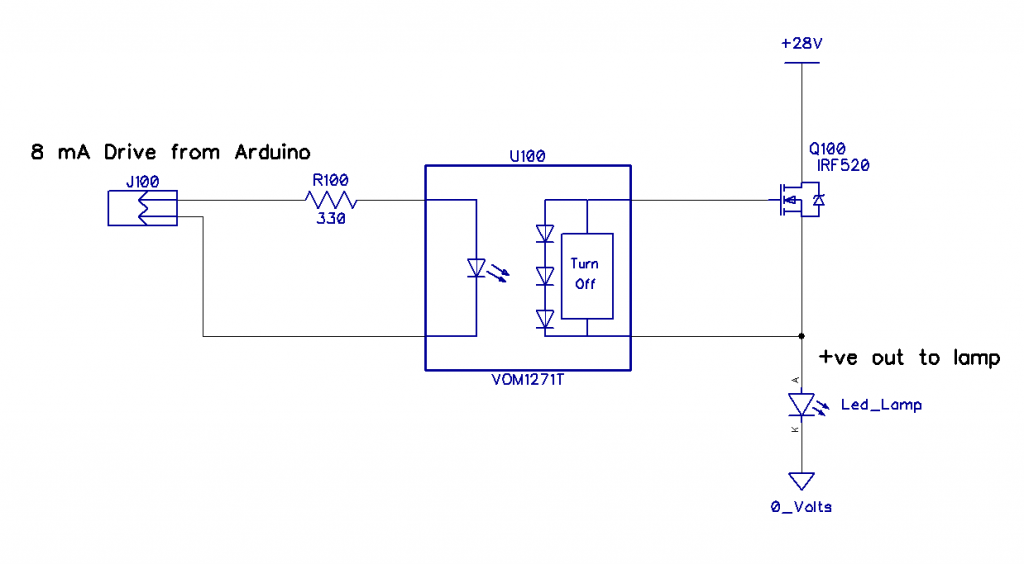 Cheers Mike |
||||
| PeterB Guru Joined: 05/02/2015 Location: AustraliaPosts: 669 |
G'Day Mike I think you have solved the problem but it will be interesting to see what Bob thinks. Your block labeled "Turn off" reminds me of a flow chart we had at work in the middle of which was a block "here a miracle occurs". Do you have any idea how the blasted thing works? Peter |
||||
| Mixtel90 Guru Joined: 05/10/2019 Location: United KingdomPosts: 8911 |
That is very, very neat. I didn't know that such a beast existed. You put aout 10mA through the opto-isolator input diode. That's typically 1.4v voltage drop. It won't run below 5mA because the device uses some of that volt drop to run a dc/dc converter. It looks like the 3-diode receiver on the opto-isolator might operate in reverse. While the input is "on" the converter puts out about 8v relative to the source of the N-channel mosfet., the opto-isolator receiver is out of circuit. That switches the mosfet on as it's well above Vgs. While the input is "off" the converter output drops to zero, the three diodes are back in circuit and will pull the gate voltage down to less than 1v above its source - well below Vgs. (The "Turn Off" block is as shown on the data sheet - they aren't particularly forthcoming. :) ) It's one of those "I wish I'd thought of that" things. :) Actually it's not that dissimilar to what I last described. I used a gate-source resistor to switch off, giving a slower switching time. I used an opto-isolator to switch the gate up to a dc/dc converter voltage, giving a slower switch on because the turn-off resistor was still in circuit. But I was a long way from powering the dc/dc converter from the opto-isolator input circuit. lol Edited 2021-08-01 17:20 by Mixtel90 Mick Zilog Inside! nascom.info for Nascom & Gemini Preliminary MMBasic docs & my PCB designs |
||||
| Turbo46 Guru Joined: 24/12/2017 Location: AustraliaPosts: 1693 |
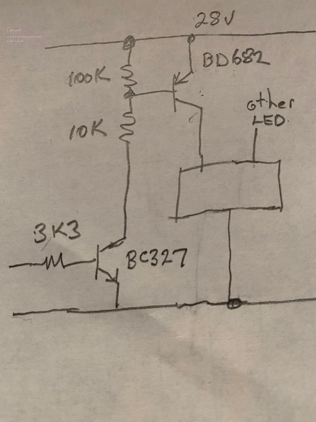 Using my circuit and Peter's BD682: Choose the base to emitter resistor to be 100k (pretty standard) just to make sure the BD682 does completely turn off when no base current is present. The BD682 has a minimum gain of 750 so assuming the LED wants 1A, the base current needs to be: 1/750 = 0.0013A or 1.3mA. Say 3mA to be sure. So the base driving resistor needs to be 28v/0.003A = 9.333k say 10k because we are being generous with the 3mA anyway. 28v/10000ohms = 2.8mA base current - good enough. Choose the PNP transistor to drive the base current for the BD682 as almost any small signal transistor with a minimum gain of 50. That transistor needs to supply 3mA (OK 2.8mA) so it's base current needs to be 3mA/50 = 0.06mA say 1mA to be really sure. Assuming 3.3v switched from the micro - the base resistor should be 3.3v/.001A = 3300 ohms. If the micro is switching 5v then it will turn on even harder. A base to emitter resistor is not needed for this one because the micro's output will switch very close to zero. This is untested but it should be OK. The BD682 WILL need a heatsink because the maximum collector - emitter saturation voltage is 2.5v so at 900mA that's nearly 2 and a half watts! Bill Keep safe. Live long and prosper. |
||||
| bob.steel Senior Member Joined: 27/02/2020 Location: AustraliaPosts: 188 |
Ordered 10 for $15 aud Mike so well see.Thanks |
||||
| Solar Mike Guru Joined: 08/02/2015 Location: New ZealandPosts: 1214 |
For those of you wondering how that VOM1271 works: Internally its a bit like a tiny PV panel with a bunch of infrared sensitive diodes, that generate a voltage. They also have active circuitry to quickly dump the gate current when switched off. Makes them quite slow to turn the mosfet on as it charges the mosfet gate capacitance, fast to turn off. Another type of more sophisticated chip uses a RF modulation signal internally see this example Si8751-2, you will find them in solid state switch devices. Cheers Mike |
||||
| PeterB Guru Joined: 05/02/2015 Location: AustraliaPosts: 669 |
All that for $1.50. What is the world coming to? You young blokes don't realize how easy you have it.  Peter |
||||
| CaptainBoing Guru Joined: 07/09/2016 Location: United KingdomPosts: 2171 |
Thanks for the description - it helps but I am still not seeing how it generates the correct charge for the gate (i.e. VDD + VGSth) - there is no reference to VDD, how does it "know" what to put on the gate? incidentally, here is the P-CHANNEL logic level beastie I use in my "soft power" circuit NDP6020P ... and said circuit (this is the "afterthought" add-on version  ). Ground the /START signal (push button), uC starts up and asserts a HI on KEEPALIVE. I retro fitted this on a lot of my battery powered kit and it is now designed in on new stuff. Usually on a timer that gets set (to, say, 10 minutes) on any activity. The timer is decremented at regular intervals and if it reaches zero... ). Ground the /START signal (push button), uC starts up and asserts a HI on KEEPALIVE. I retro fitted this on a lot of my battery powered kit and it is now designed in on new stuff. Usually on a timer that gets set (to, say, 10 minutes) on any activity. The timer is decremented at regular intervals and if it reaches zero...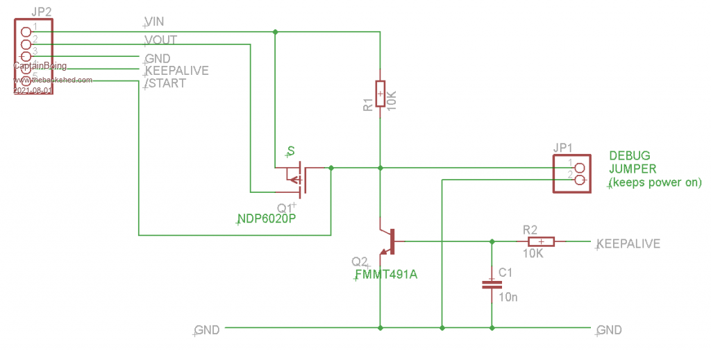 Edited 2021-08-01 19:08 by CaptainBoing |
||||
| Solar Mike Guru Joined: 08/02/2015 Location: New ZealandPosts: 1214 |
@PeterB, "You young blokes don't realize how easy you have it." Hmm I can remember building 1 valve TRF radio's whilst at school, so not that young. @CaptainBoing, " it helps but I am still not seeing how it generates the correct charge for the gate (i.e. VDD + VGSth) - there is no reference to VDD, how does it "know" what to put on the gate?" Doesn't care about VDD, generates a set voltage between Source - Gate pins of the mosfet, up to 10 volts, depending on input isolated drive current, generally many mosfets have a 10v on rating spec. Mike |
||||
| CaptainBoing Guru Joined: 07/09/2016 Location: United KingdomPosts: 2171 |
nice, so it's like an isolated charge-source just around the FET. Some brains are working with design of that device!  Edited 2021-08-01 20:35 by CaptainBoing |
||||
| PeterB Guru Joined: 05/02/2015 Location: AustraliaPosts: 669 |
Mike. I used a 1k5 that cost Mum 2/6 from Radio & Hobbies. It took me a long time to get it going because I didn't know what to do with the unused electrodes. Peter |
||||
| Solar Mike Guru Joined: 08/02/2015 Location: New ZealandPosts: 1214 |
Too sophisticated for me, think I used some sort of very basic Triode with regenerative feedback; over 50 years ago, about the same time germanium transistors were becoming available; haven't things progressed.... |
||||
| PeterB Guru Joined: 05/02/2015 Location: AustraliaPosts: 669 |
Tell me about it. I'm 83 so it would be 70 years ago I finally got that 1k5 up and running. But it has been wonderful (life not the 1k5)Peter |
||||
| Mixtel90 Guru Joined: 05/10/2019 Location: United KingdomPosts: 8911 |
My dad took me to Southport to get the bits to build my first 1-valve set. I'd done a few crystal sets by then (not cat's whisker types!). It had a 1T4 valve, I remember that much. :) It worked after a fashion... DOH! - of course the VOM1271 is PV. It says so on the data sheet and I'm to dim to read it properly. lol Still a very neat way to do it though. The only problem round here seems to be in buying it in small quantities. Mick Zilog Inside! nascom.info for Nascom & Gemini Preliminary MMBasic docs & my PCB designs |
||||
| PeterB Guru Joined: 05/02/2015 Location: AustraliaPosts: 669 |
There is something special about your first car, your first girlfriend and your first 1 valve radio. For a long time I worried that youngsters would miss out on the last bit because you can buy a clever radio for the price of the bits to build anything. Is that why there are so few young people on TBS? I hope not. Peter (the philosophical) |
||||
| The Back Shed's forum code is written, and hosted, in Australia. | © JAQ Software 2026 |
