
|
|
Forum Index : Microcontroller and PC projects : Will the Pico directly drive this MOSFET?
| Author | Message | ||||
| Paul_L Guru Joined: 03/03/2016 Location: United StatesPosts: 769 |
The coils of the big relays enclosed in steel boxes require less than 100 ma at 28 v.a.c. 60 Hz. The heat pump compressor is a 240 v.a.c. Copeland Scroll Compressor with a starting current of 54 A and a running current of 22 A. It starts with a great big relay. That compressor will trip off my 10 KVA natural gas backup generator on startup. Paul in NY |
||||
| Mixtel90 Guru Joined: 05/10/2019 Location: United KingdomPosts: 8682 |
Even Chinese relays shouldn't have a problem switching those coils. That's a low starting current for a running current of 22A. For a "traditional" single phase motor with plenty of iron in it the starting current is usually around 6X to 7X the full load current, which would put your motor starting current at about 132A. I know modern high-efficiency motors are a lot better, but I didn't know they were at that stage now. :) I'm wondering if it has some sort of electronic start. Or is it 240V 3-phase? I see that you're in the US so that's definitely a possibility. If you are starting motors on a generator then look at the kW ratings of both, not the current. kVA is what it says - volts x amps. It doesn't take power factor into consideration. Generators and motors are often not happy together and you often need a bigger genny than you might think. �:( Edited 2022-06-11 18:17 by Mixtel90 Mick Zilog Inside! nascom.info for Nascom & Gemini Preliminary MMBasic docs & my PCB designs |
||||
| phil99 Guru Joined: 11/02/2018 Location: AustraliaPosts: 3086 |
The trick I use to get the heat pump to run on the generator is to first load it up with a 2kW heater then switch that off and the heat pump on at the same instant. With the throttle already open before it gets hit with the starting current it can usually make it through the surge. |
||||
| lizby Guru Joined: 17/05/2016 Location: United StatesPosts: 3699 |
So for switching on 12V and 4+A for LEDs with an IRL540 (etc.) MOSFET, I've been using a 680R or 1K gate resistor and a 100K pull-down resistor. I may be PWMing at 1kHz. If I understand Volhout correctly (other than the spike issue), that gate resistor may be too high, and may slow down the turning on of the MOSFET when PWMing which may leave it in the linear range for too long, resulting in overheating (perhaps at higher amperages). What would be the ideal gate resistance if driving such a resistive load? 3V3/220R would be 15mA. Would that be more nearly correct for the Picomite? Is there a better (lower) PWM frequency which would not result in perceptible flicker? (I'm at a stage at this point where what I'm doing appears to work, and if it ain't broke, . . . -- but if I can do better, I'd be happy to adjust (and yes, if I try to drive an inductive load, I'll use a driver or opto coupler).) PicoMite, Armmite F4, SensorKits, MMBasic Hardware, Games, etc. on FOTS |
||||
| Volhout Guru Joined: 05/03/2018 Location: NetherlandsPosts: 5806 |
Hi Guys, Just wanted to show you some graphs from a simulation, about driving a mosfet from a picomite pin. There where circuit suggested by several, and I want to shed some light on the proposals, and show what the impact is. Let's take a standard IRF840 FET (500V 8A) switching a resistive load of 1A at 300V. The gate is driven with 10V. 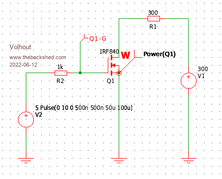 In the schematics you can see that the series resistance is 1k ohm (just for the demo). The waveform at the gate is shown below. 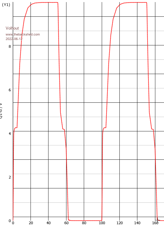 There is no steep switching ON and OFF, but there is a flat area in both rising and falling edge. This is caused by the internal capacitance of the MOSFET. While the gate voltage rises, the FET starts to conduct, the drain voltage falls , and while falling it couples negative charge into the gate. Like a feedback. To see the effect on the FET, see this picture 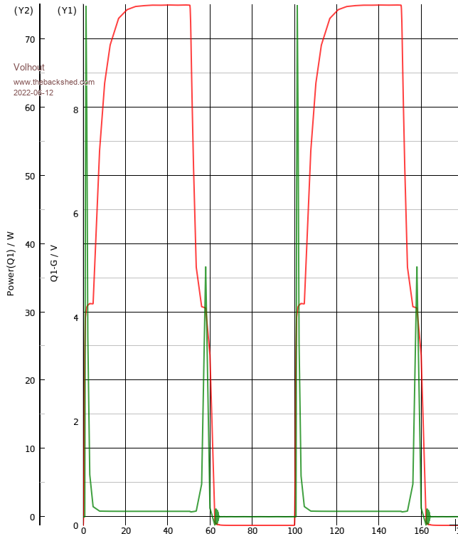 This is the same picture, but in green is shows that the dissipation inside the FET. You can see that despite the FET is only switching 300W, it dissipated peaks of 70W during switching. Again, for a FET of this type, that is not dagerous, but you will be able to feel that the part is a bit warm if you drive it with 1k in series with the gate. If you drive the gate with 50 ohm, the FET switches faster, and although the peak dissipation is 60W, the duration is far less, so the part will not heat up at all. 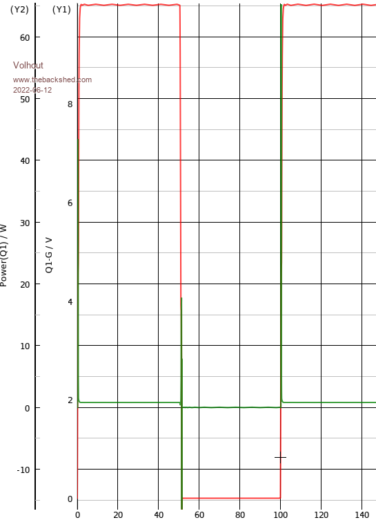 So if someone wants to drive a FET with 10k series resistance, using an optocoupler, you may want to look at a heatsink for the FET. Needless to say that the bigger the FET (more current) the bigger the silicon, and therefore (most cases) the bigger the capacitance. If you want to drive your MOSTFET from a picomite, you should use a high current capable driver. -or- accept the FET heats up. PicomiteVGA PETSCII ROBOTS |
||||
| Tinine Guru Joined: 30/03/2016 Location: United KingdomPosts: 1646 |
OK the forum fell asleep so I'm gonna tell about my phone conversation. This FET thing is for a bus-driver's seat heater. The client was talking about 200 units before winter and now it's 1800 units... What the �  ??? ???Apparently it's a retrofitting and 1800 is only one of several operators. Since when have buses been cold enough that the drivers need heated seats...and so urgently? Verbatim from London Transport: "This winter, we're bringing back Covid. Every bus will have permanently open windows and passengers will just have to tolerate it. However, we need our drivers to be warm" If you still don't understand that this cr@p was all fake, I dunno what to tell you. �  Craig Edited 2022-06-16 02:02 by Tinine |
||||
| Mixtel90 Guru Joined: 05/10/2019 Location: United KingdomPosts: 8682 |
Sounds like a nice job for JLCPCB to source the bits and do the assembly when they make the PCBs. :) Better make it all surface mount for their pick & place. Mick Zilog Inside! nascom.info for Nascom & Gemini Preliminary MMBasic docs & my PCB designs |
||||
| Tinine Guru Joined: 30/03/2016 Location: United KingdomPosts: 1646 |
Just told them that I can't get excited but they won't let it go. This tells me that they have carte blanche (government money). Anyone here want the job? Makes me wanna hurl. I'm not shy about pricing for a serious profit but when it comes to profiting from the biggest scam in human history...Eff-that!!! Craig (unmasked, untested and definitely unjabbed) |
||||
| Mixtel90 Guru Joined: 05/10/2019 Location: United KingdomPosts: 8682 |
They are just being cheapskates. This lot know how to make proper bus drivers' seats. Or if you want a kit ... :) Edited 2022-06-16 03:40 by Mixtel90 Mick Zilog Inside! nascom.info for Nascom & Gemini Preliminary MMBasic docs & my PCB designs |
||||
| Paul_L Guru Joined: 03/03/2016 Location: United StatesPosts: 769 |
Hi Mick. [ENGINEER HAT ON] Yes, it's a very low starting current! It's not magic and there has been nothing new in motor design since George Westinghouse and Tom Edison figured out how to design the lap and plex of a DC motor in order to generate rotating torque in the rotor in a DC motor. A 3 phase AC motor generates torque by reproducing the magnetic vector existing in the generator while the 3 phase armature rotated within the field. A 1 phase AC motor generates a magnetic field which flips 180� with each reversal of polarity in the power voltage. A 1 phase motor needs some way to generate torque to start can be produced by phase shifting with a starting capacitor in series with the start coil. A 1 phase motor winds up needing much higher starting inrush current to get it spinning than a 3 phase motor would need. A DC motor needs a commutator and brushes for each set of windings. It can only generate a single magnetic field otherwise. The commutator and brushes enable it to generate a magnetic field which rotates in discreet steps thereby dragging the armature around with some slip. The trick here is that it is a Copeland Archemedian Spiral Scroll Compressor. This is one of those machines that you don't believe could actually work. It contains scroll which orbits (not rotates) within a volute. One video is worth a thousand words ... take a careful look. https://www.youtube.com/watch?v=dsabYhhOko0 https://www.youtube.com/watch?v=yNgqI4XPUZc https://www.youtube.com/watch?v=iU5PVinDyNQ https://www.youtube.com/watch?v=EA47Ra8n24Q When the motor is stopped the moveable scroll retracts vertically from the fixed scroll. When the motor starts there is no load from the retracted scroll, but when the loose scroll begins producing very slight freon pressure the scroll is forced upwards until it engages the fixed scroll and then develops higher pressure and requires more torque from the motor.[ENGINEER HAT OFF] Copeland calls this "unloading". It's a mechanical trick which requires much lower starting current. Paul in NY Edited 2022-06-16 06:40 by Paul_L |
||||
| Tinine Guru Joined: 30/03/2016 Location: United KingdomPosts: 1646 |
OK, I'm officially confused. There is no quarrel over cost here. They seem not to care because it's government money. I figure a conservative �30 profit per unit but I really don't want it. Why are we going off on a tangent? Craig |
||||
| Mixtel90 Guru Joined: 05/10/2019 Location: United KingdomPosts: 8682 |
Just a bit of thread drift from a discussion between Lizby and Paul_L, Craig. Something I got used to as a mod on another forum. lol In your case I genuinely have difficulty in figuring out *why* the bus people want this particular solution from someone they probably know very little about when there are bus builders out there with years of expertise in putting heaters into driver's seats and who probably already have many standard components exactly for this (those Chinese kits won't be an original invention). All I can think of is that they want something to undercut those manufacturers by a fair bit so that they can pocket the difference and walk away - leaving the hapless installer to pay any additional costs if the thing doesn't work perfectly, on every installation, forever. They might even try to hold on to a conditions of purchase so that you couldn't freely sell them to anyone else when the contract has finished - and so that they get a cut out of each of those sales if you do. They would claim that they paid for the original design as part of their order so the intellectual property is owned by them. I've grown so cynical as I get older. :( Mick Zilog Inside! nascom.info for Nascom & Gemini Preliminary MMBasic docs & my PCB designs |
||||
| The Back Shed's forum code is written, and hosted, in Australia. | © JAQ Software 2026 |
