
|
|
Forum Index : Electronics : Good money after bad - Solar upgrade time
| Author | Message | ||||
| wiseguy Guru Joined: 21/06/2018 Location: AustraliaPosts: 1297 |
I have seen and experienced this exact phenomena, I consider it to be a nuisance type issue. I put it down to random probably nano/pico second differences in the nano just executing the code. If enough of these slight perturbations occur in the same direction ie always on the positive cycles the Toroid Flux wanders towards (very mild) saturation on one side of the half cycles but eventually it slowly wanders back the other way. Sometimes there is no noise for multiples of minutes, even tens of minutes but it is never gone. The corresponding slight increase in current during the mild saturation would also be expected. The reason this does not continue on to become a real issue is that the slight error causing it means there is not enough energy in the error to put it into greater saturation. Note a toroidal transformer in an amplifier or similar device can make a hell of a "boing" sound followed by a few cycles of hum that decreases rapidly, if you catch it on the wrong part of the cycle after a turn off turn on event. I mention this to illustrate that the tendency of a transformer is to try to reach a level of equilibrium after an upset, maybe the AC has a natural tendency to demagnetise & remove any saturation naturally. The Power PCB FET holes were made to accommodate a standard 3.6mmOD TO220 Bush, and with the long necked variety yes the bush shoulders continue into the TO247 FET hole. Something similar to the Digikey part 12SWS0400, it is better not to have to drill out the circuit board plated through holes.... Edited 2025-04-30 00:10 by wiseguy If at first you dont succeed, I suggest you avoid sky diving.... Cheers Mike |
||||
| oreo Senior Member Joined: 11/12/2020 Location: CanadaPosts: 133 |
Interesting. Thanks for the update Mike! Greg |
||||
| analog8484 Senior Member Joined: 11/11/2021 Location: United StatesPosts: 204 |
Thanks for the explanation. I was wondering because I've seen quite different ratings from different manufacturers for similar size/weight transformers. |
||||
| analog8484 Senior Member Joined: 11/11/2021 Location: United StatesPosts: 204 |
Thanks for the video. It sounds like some kind of harmonic resonance. Especially odd that it happens under load. Not sure if it makes a difference but I remember seeing the timer resolution in the Nanover is relatively low and accuracy for 60Hz is not as good as the 50Hz config. |
||||
| analog8484 Senior Member Joined: 11/11/2021 Location: United StatesPosts: 204 |
Not sure if it's still used in the latest Nanoverter code but I remember seeing a simple fixed correction for half-cycle balance that is supposed to be tuned for each inverter? Perhaps that's at play here. |
||||
| KeepIS Guru Joined: 13/10/2014 Location: AustraliaPosts: 2197 |
You are going back to the early code development days and "per inverter" would imply a kludge, obviously nothing like that here. I assume you are referring to stability, so no, both are stable and adjustable slightly in frequency (in mine) There will be small differences between 50Hz and 60Hz with a given Toriod, however if it's wound correctly you should see no real difference in operation, maybe slightly lower idle at 60Hz. NANO:Inverter V 8.2ks - Linux AvrDude GUI script V4.1 |
||||
| wiseguy Guru Joined: 21/06/2018 Location: AustraliaPosts: 1297 |
Something else that affects the stability of each half cycle of the sine is how well the timing variations are matched between the 4 FET drive optocouplers. There are propagation delays (for both, high going and low going events) + a distortion component in the optocouplers. These are specified at 25 Deg C and no doubt can also vary with temperature, along with the capacitor stability for the dead time capacitor in parallel with the Opto LEDs. Now consider the 4 combined FETs on/off rise & fall time for each leg of the bridge as well. So is it any wonder that there may be slight differences between the integration of the total switching on and off times for each half cycle? I think its actually surprising that there are only minimal issues. Perhaps prior matching of each sides of the bridge H & L Opto couplers timing would pay good dividends - maybe some builds fluke the matching better than others? If at first you dont succeed, I suggest you avoid sky diving.... Cheers Mike |
||||
| KeepIS Guru Joined: 13/10/2014 Location: AustraliaPosts: 2197 |
Thanks, I had not thought of most of those, the list is growing longer. Multiply by two for Dual power boards and Toroids, or maybe they cancel out  NANO:Inverter V 8.2ks - Linux AvrDude GUI script V4.1 |
||||
| oreo Senior Member Joined: 11/12/2020 Location: CanadaPosts: 133 |
Toroid Transformer Noise I spent about 25 years working for a prominent Canadian speaker company who used transformers in many of their products. Audio customers did not want to hear any transformer noise, so we spent a fair bit of time working to reduce transformer noise. Skip to the recommendations in the next post if you just want to know the recommendations. Most of the transformers we used, were common EI style transformers and we worked with just 2 manufactures to determine what worked best. One of the suppliers built a transformer audio testing chamber, so they could accurately judge the effect of process changes. In a nutshell, for EI transformers it was found that putting them through vacuum impregnation varnishing twice was the most cost effective way of getting a particular design as quiet as possible. Of course we also used isolation mounting techniques and cabinet/chassis designs which reduced the transmitted noise and the flux density used in the design influenced things significantly. While most powered subwoofers used EI transformers, nearly all the receivers and preamp/amplifiers we built used toroidal transformers. While toroid transformers are normally quieter than EI designs, we had more issues with toroidal transformers than we did with EI transformers. When you turned on the product, the toroid would make a louder buzz than normal, which would make the customer hyper sensitive, listening for any noise. At one point, we were dealing with 2 Canadian suppliers, 3 Chinese suppliers and Noratel which built product in Sri Lanka and had issues from all our suppliers. From any particular production batch, there would be some noisy transformers. Some suppliers were worse than others. We took apart product and found that no-one was varnishing the transformers. We approached all our suppliers and asked them to varnish the transformers and not one of them said they would do it. Our local supplier with the sound chamber were more open, and said they would do some testing for us. They tested varnishing the core, and varnishing the windings. The results were not intuitive. Varnishing the core increased the noise. Varnishing the windings had no measurable effect. Keep in mind that these results are for production transformers, with tight windings and production controls that enforce good build practices. This testing was done with low distortion 50 and 60 Hz power sources. Greg |
||||
| oreo Senior Member Joined: 11/12/2020 Location: CanadaPosts: 133 |
Toroid Build recommendations 1. Low Flux Density. Many are doing this already to get low standby power draw, and it has a major impact on noise. (my transformer is a commercial design, which I have improved upon slightly, but probably has a relatively high flux density compared to most of you) 2. Isolate the transformer from the case. Most transformers are provided with neoprene pads. Adding further isolation will help as these are pretty thin and IMO not the right durometer. Rubber isolate hold down screws and don’t tighten them too tightly. (right now I have my transformer resting on nylon plastic bars. This is making the noise worse) 3. Make chassis with dense sound absorbing material. KeepIS has a chassis made of wood/MDF which is a good choice for noise control. My chassis is aluminum/steel and could benefit from some damping. (I ordered some damping material for a car project and plan to use a bit of it in my Inverter) I will report on it's effectiveness. Of course since this is DIY, other factors will come into play. If you make your windings loose, then you may benefit from Varnish and as long as you don't varnish the core, it may be a good idea as an insurance measure. Greg |
||||
| analog8484 Senior Member Joined: 11/11/2021 Location: United StatesPosts: 204 |
Kinda of surprising result. Good to know no varnishing needed/recommended is another plus for toroidal transformers. |
||||
| analog8484 Senior Member Joined: 11/11/2021 Location: United StatesPosts: 204 |
It seems the presence of DC voltage is the most likely cause of the transformer noise. I wonder if the DC voltage of the power board output could be measured to show noticeable increase when the noise occurs? |
||||
| KeepIS Guru Joined: 13/10/2014 Location: AustraliaPosts: 2197 |
Cabinet is 19mm hardwood ply, the Base is a separately constructed Heavy "Box sectioned" frame, containing two 100mm heavy cast framed 240Vac fans, one under each Toroid, fans completely isolated from the frame which is skinned with thin 3mm hardwood ply and supported by five 200kG wheels. You would think it would be sound deadening, but the base is partly hollow, it has resonance and easily transfers any noise from the effects of unbalanced AC loads in the Toriods. I doubt that anything you do will stop a Toroid CORE from ringing when abused. The potted ones still hum in GTIs. However I understand that you have noise at Idle. I can reproduce a similar noise on the bench test unit, I'm not suggesting it's the cause of your problem, but the results are similar. I think I know why this happens in the test unit, it may have something to do with what I found when trying to set static resonance in a Toroid via the Secondary CAP value, with a simple test to prove what I was seeing, I realized it was like trying to heard cats, it's why we have soft ramp down, as well as Soft ramp up. Wiseguy suggested flux walking and getting closer to saturation, either by Toroid design decisions or inducing flux to move towards saturation, or worst case both, and this certainly appears to be a likely cause. To your point on Flux density, my Toroids have an effective 280Vac secondary. With a 14 turn primary they are still Quite when "AC->AC" testing at 275Vac output, the saturation power curve knee hits hard past 280Vac, hum/buzz/hi current appear quite rapidly as I move into saturation past 280Vac. They are silent 99.9% of the time at 240Vac in the Inverter, they are silent and 240Vac regulated just above 40Vdc. DC voltage on the Power boards should not change at idle with a few watts of power cycling. I have two permanent DSO monitor output ports mounted into the front of the Big inverter. Each connected to an output from two 400A Hall Sensors monitoring each Power boards DC input current that drive two peak hold DC pulse analogue displays. And I just remembered the following because I tested for it at the time. It was Poida who suggested a current sensor on the DC input could be used to identify the beginning of saturation, with small current peaks appearing on the DC current waveform, the peaks coincide with Zero crossing of the AC waveform, I may look at the Test setup again and see if I can see that when I induce the buzzes. Edit: It appears that placing a Hall current sensor over one of the cables between the Power board and the Toroid may highlight the beginning of saturation in greater detail. BTW: There is a reason I don't use metal underneath these two x 34Kg Toroid stacks, it has to do with purposeful design choices I made for this build and part of the reason these Toroids and Chokes run so cool. . Edited 2025-05-06 08:35 by KeepIS NANO:Inverter V 8.2ks - Linux AvrDude GUI script V4.1 |
||||
| oreo Senior Member Joined: 11/12/2020 Location: CanadaPosts: 133 |
So the Wiseguy inverter has been running reliably for about 7 weeks, and I have been slowly dialing in the 60Hz frequency. I have the software at 60+ and external clocks that use the line frequency are losing ~17 seconds per day. This is pretty good, but I would like to improve it if possible. FYI, I measured the frequency of the 3 Nano processors I have and they vary significantly (from 15.860-15.947mHz). Anyway, yesterday I noticed the inverter was not running and was displaying this message. 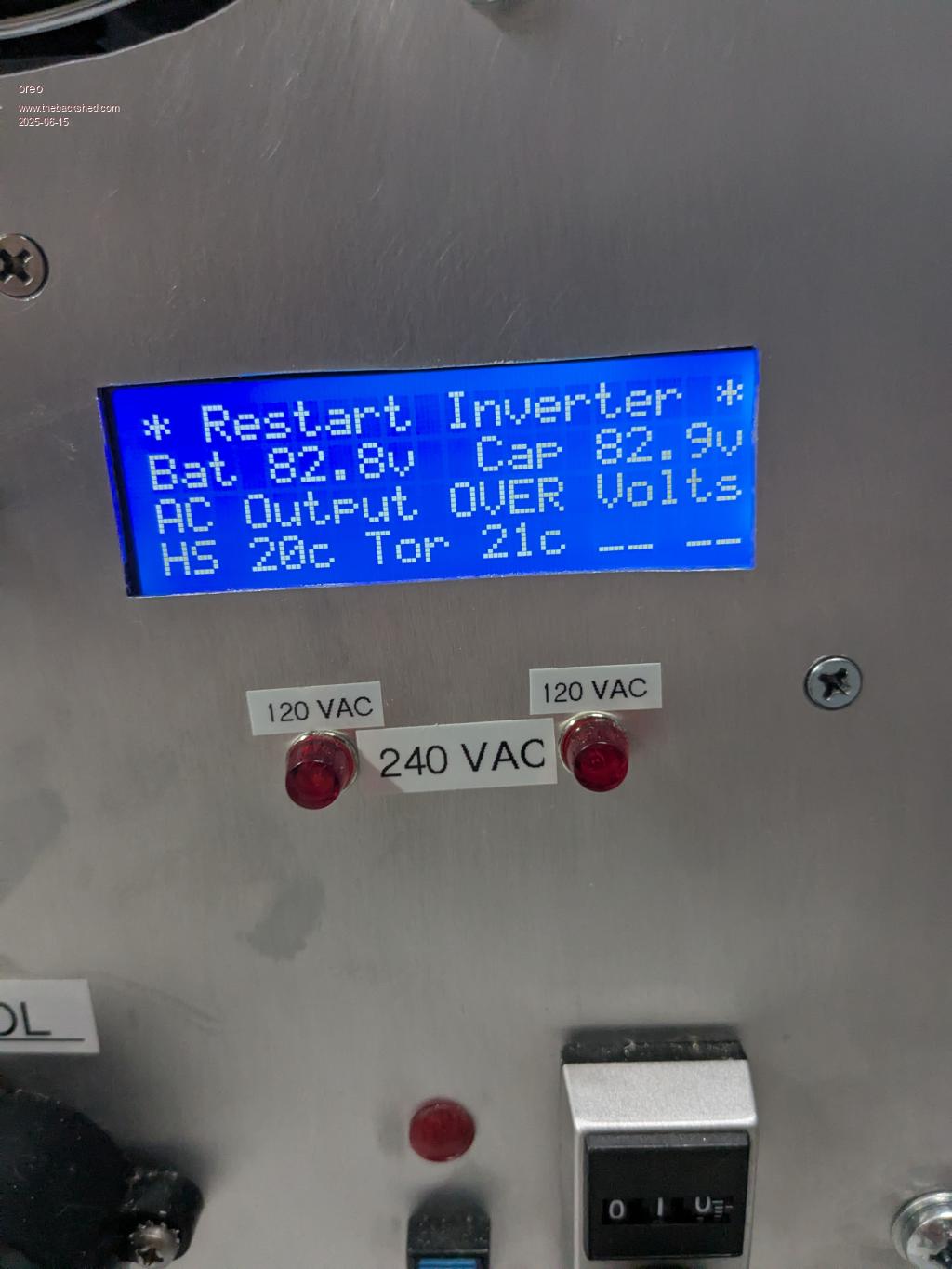 I shut off and restarted the inverter, and it started and settled back to 240vac. I left it and when I returned an hour later, it had tripped again. Further attempts to restart the inverter resulted in it immediately tripping with AC output overvoltage. So I monitored the voltage on pin A0 of the Nano. With a separate 120v source plugged into J2, I measure 1.4 volts on A0 and the display reads 120VAC. This is what it should be I think. When I reconnect J2 back to the output of the inverter and turn it on, the voltage on A0 ramps up to 3.0v. I tried increasing the over voltage trip to 280v, and it still tripped. The display briefly displayed 290vac during the attempted power up. 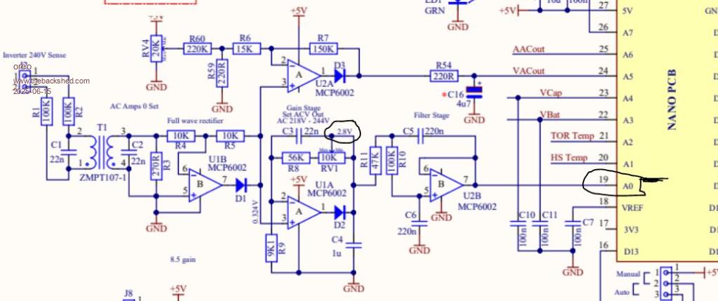 Since the voltage being fed into the Nano on pins A0 and A5 looks to be correct, I figured there must be a problem with the Nano itself. I swapped it out with another, and after getting the new Nano set up, it does the exact same thing. The 5v power supply measures 5.03v and the 12v supply looks good too. The output of the inverter when in test mode is a perfect looking sine wave. Any suggestions on what to check next? I do have a spare board, which needs just a few components so I will build that up and swap it. (probably tomorrow) Right now for grounding, I have the .01uf Capacitor in place (near the LR mounting screw), and have the cast heat sink directly under the board. I believe the preferred method would be to have an additional isolated plate under the Nano, which is attached to the .01uF capacitor. I will try this first. thanks Greg |
||||
| wiseguy Guru Joined: 21/06/2018 Location: AustraliaPosts: 1297 |
Hi Greg, I have essentially zero experience with the KeepIS software so my comments are only general in nature. From memory I think the control feedback voltage on A0 should be ~ 2.8VDC when the inverter is in regulation, you mentioned it goes to 3V? When checking the A0 voltage only measure it on the Nano module itself, in case the Nano module pin/socket to the controller PCB is not mating properly. I note that at 120V you measured 1.4V so at 240 it should be 2.8V, which is where it should regulate, increasing A0 past 2.8 should reduce the PWM to minimum. The fact the output regulated to 240V ok after a restart before tripping again later sounds like an intermittent fault so check all AC voltage feedback connections, J2 plug integrity etc. It could even be a poor soldered joint on the controller PCB along the J2 to A0 chain. If you have made any tweaks to the software, can you revert back to the original software from KeepIS to see if that cures it, but it sounds more hardware than software! I assume the overvoltage monitor and shutdown is derived from a setpoint on A5? Everything happens for a reason - keep hunting, the cause will eventually be revealed. Good luck! Edited 2025-06-16 01:56 by wiseguy If at first you dont succeed, I suggest you avoid sky diving.... Cheers Mike |
||||
| oreo Senior Member Joined: 11/12/2020 Location: CanadaPosts: 133 |
Thanks for the quick response Mike. Funny how the brain works (or doesn't) at times. With 120v on J2 I was measuring ~.17v at the input of U1A pin 3, while at the output (after the diode) I thought I was measuring 1.4v but I was actually measuring .14v. So in my head I was thinking the circuit around U1A was working properly, when it wasn't. First off, I measured the components and everything seemed to be ok. I then swapped in a new U1 (MCP6002) and the circuit started working. I re-soldered the pins on the socket, swapped the old part back in and it stopped working. Seems strange to me, but it appears that the IC has failed. Anyway, things are now back in operation. thanks again Greg |
||||
| KeepIS Guru Joined: 13/10/2014 Location: AustraliaPosts: 2197 |
Been fighting the seasonal bugs the last few days and just saw your post. Great to see you solved it with input from wiseguy  Just for future reference for anyone else hunting a problem like this, if you were getting an over voltage only at reset or power up then you must use a DSO connected to the over voltage ADC pin, the DSO may need to be triggered to capture the single spike causing this from a circuit fault, otherwise you won't see it. In your case you found a hard IC fault, hopefully only bad luck. I do worry about the quality of the components we end up with, but LLC seem to be our best source, I think (from memory) you sourced most of your components from them. The AC frequency thing for these stupid mains synced devices is a problem both at 50Hz and 60Hz I could give you the option to increase it a bit more. I have only one device that syncs and it's a newer Inverter Microwave, it's about 5seconds a day. There is no easy way to get it closer without screwing around, it's not worth the time or effort as it would require a hardware mod to the Nano, and change with every nano. Great to see the inverter still running well  NANO:Inverter V 8.2ks - Linux AvrDude GUI script V4.1 |
||||
| oreo Senior Member Joined: 11/12/2020 Location: CanadaPosts: 133 |
KeepIS -hope you're feeling better soon. Actually the Op-Amps came from Digikey. Perhaps I mishandled them. I was very surprised that one had failed. Regarding the frequency of the inverter. Thanks but I think I am going to play around with the 2 SI5351 boards I have and see if I can get one working with a couple of nano boards. I am shocked at how different the oscillation frequency of each nano board I have is which would make a software solution difficult. Greg |
||||
| KeepIS Guru Joined: 13/10/2014 Location: AustraliaPosts: 2197 |
Precisely Thanks, still suffering  NANO:Inverter V 8.2ks - Linux AvrDude GUI script V4.1 |
||||
| oreo Senior Member Joined: 11/12/2020 Location: CanadaPosts: 133 |
So I finally got around to installing the last 3pcs of the 535w panels I purchased in February last year. For the last year or so, I have been using 3pcs of 535w and 3pcs of old 250w units. Anyway, when I removed the 3 older panels I noticed a burn mark on one of them. 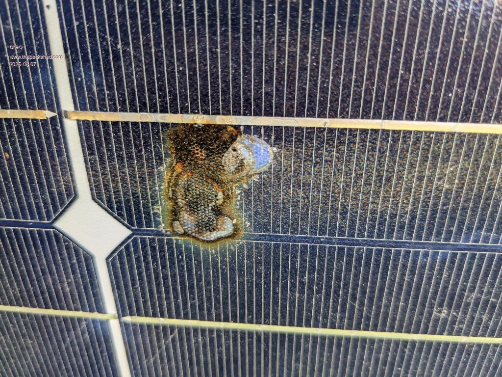 Looking from the bottom 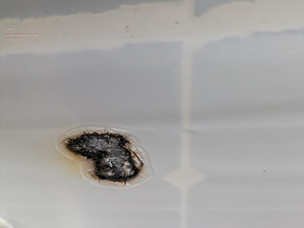 It seems like an odd location for a burn, as I would have thought that it would center on a bad metallic track. This burn looks to be centered in the solar cell array itself. Is this type of thing common? At least the replacement panels are bifacial which means there is glass on both sides of the panel. Greg |
||||
| The Back Shed's forum code is written, and hosted, in Australia. | © JAQ Software 2026 |
