
|
|
Forum Index : Microcontroller and PC projects : Picocalc done properly?
| Author | Message | ||||
| toml_12953 Guru Joined: 13/02/2015 Location: United StatesPosts: 685 |
I'm ordering one from whoever makes them anyway. I can't wait! I'm tired of the limitations of PicoCalc. |
||||
| Mixtel90 Guru Joined: 05/10/2019 Location: United KingdomPosts: 8964 |
I have an idea.... 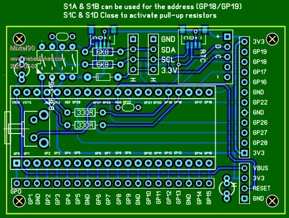 The QWIIC connectors are optional and are powered from the Pico's supply, which also feeds the pullups. The two 4-pin I2C headers are connected to the remote device's supply. The Pico's 3V3 is fed from a diode from the remote supply so it will be powered by either the USB socket or remotely. This isn't really ideal as there will be volt drop from the external source but I didn't want to have to squeeze a mosfet in! EDIT: Still in design. I've just squeezed a CR1220 on board so RTCs with dead batteries can be reused. I don't like throwing them away. :) There's also a solder blob link to disconnect the remote 3V3 supply. That might be useful in some cases, like where the supply is from a low current source. . Edited 2025-07-07 02:02 by Mixtel90 Mick Zilog Inside! nascom.info for Nascom & Gemini Preliminary MMBasic docs & my PCB designs |
||||
| homa Guru Joined: 05/11/2021 Location: GermanyPosts: 651 |
Just seen through a store: https://github.com/ZitaoTech/Hackberry-Pi_Zero Store and price  : :https://www.berrybase.de/berrybase-hackberrypi-zero-tragbares-linux-handheld-cyberdeck-mit-4-display-tastatur-trackpad That should make the question of such a gadget superfluous  Yes, I know, it's a pi with linux, but ... I'm looking forward to it Peter! Hopefully I can recreate it with my modest skills. Matthias PS Personally, I would have preferred a rectangular display in portrait orientation, but as you know, you can't have everything. |
||||
| dddns Guru Joined: 20/09/2024 Location: GermanyPosts: 874 |
Have a look at elecrow and their products. |
||||
| matherp Guru Joined: 11/12/2012 Location: United KingdomPosts: 11636 |
Here is the new layout and revised schematic 87069bec-9ffb-4649-896d-5216e80dc431.pdf 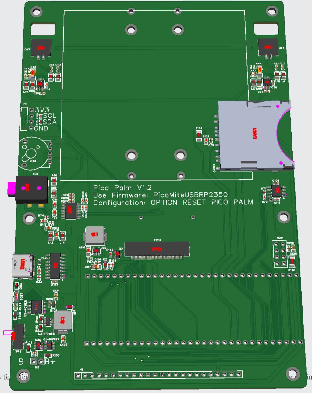 Edited 2025-07-11 03:53 by matherp |
||||
| WhiteWizzard Guru Joined: 05/04/2013 Location: United KingdomPosts: 2991 |
Looking good there Peter! Observations (take them, or leave them!). 1: I assume that is still and ESP8266 (from the shape of the connector (schematic quotes ESP32) 2: to make it easier for the user to adjust the volume when the stereo output (CN6) is in use, ideally the volume control and stereo-out connector should switch positions 3: would it be better the power switch is moved nearer to the ‘top’ of the PCB I.e. out of the way, rather than right at the bottom where it is more likely to be accidentally pressed Looking really nice with a great choice of connected parts…… |
||||
| matherp Guru Joined: 11/12/2012 Location: United KingdomPosts: 11636 |
1: just the legend wrong - thanks - also will be on the bottom of the board 2: Agree but from a layout perspective it wo4rks better keeping the audio signals clean so I'll leave it where it is. 3: Likewise, logically agree but from a layout perspective it works much better as is switching the 5V line from the boost circuit. |
||||
| tabemann Newbie Joined: 21/07/2025 Location: United StatesPosts: 6 |
If this actually becomes a thing, I would port zeptoforth (I am its primary author) to it. It already has drivers for the PicoCalc, and if this is similar in design it should not be hard to port those drivers over. |
||||
| matherp Guru Joined: 11/12/2012 Location: United KingdomPosts: 11636 |
Hi tabemann I've ordered updated cards so will see how it looks when those arrive. The big changes from the original will be: Keyboard scanned by the RP2350 (6x12 scan matrix) I2S audio using PIO to generate the I2S output DS3231 RTC on board. True memory mapped 8Mb PSRAM In addition, I've developed a RGB332 framebuffer based driver for the ST7796S display with the screen updates done on the second processor. This gives a huge performance improvement over the current driver. All my code will be available on https://github.com/UKTailwind/PicoMiteAllVersions so feel free to copy the various drivers. I won't update the github until I've tested on the new PCB. I'll be interested to try your Forth port. I used Forth many many years ago but will need to re-learn to even get started. |
||||
| tabemann Newbie Joined: 21/07/2025 Location: United StatesPosts: 6 |
I am wondering about the schematic above -- the schematic says that it uses a DIL RP2350B, but I was not aware of any sort of RP2* MCU coming in dual in-line packaging, nor am I aware of any readily available RP2350B board that breaks out 64-pin DIL to the user (e.g. while the Pimoroni Pico Plus 2 and Pico Plus 2 W use the RP2350B, they don't directly expose most of the HI GPIO's of the RP2350B to the user). |
||||
| tabemann Newbie Joined: 21/07/2025 Location: United StatesPosts: 6 |
Oh, BTW, you came up with the same solution as I did on the PicoCalc -- use an RGB332 framebuffer for my graphical terminal emulator and do most of the screen updates and terminal housekeeping (except for graphical screen updates triggered manually by the user) on the second core (even though I make it so the user can select the first core, albeit at a cost to performance, e.g. if they choose to use zeptoIP, which runs some CPU-heavy tasks on the second core). |
||||
| Mixtel90 Guru Joined: 05/10/2019 Location: United KingdomPosts: 8964 |
@tabaermann The DIL RP2350B isn't a standard part. It's one of matherp's designs and you can get them made at JLCPCB. Info here. Mick Zilog Inside! nascom.info for Nascom & Gemini Preliminary MMBasic docs & my PCB designs |
||||
| The Back Shed's forum code is written, and hosted, in Australia. | © JAQ Software 2026 |
