
|
|
Forum Index : Microcontroller and PC projects : PM Standard - HW Watchdog issue...
| Author | Message | ||||
| Mixtel90 Guru Joined: 05/10/2019 Location: United KingdomPosts: 8911 |
This would be nice as a little 4-pin module with 0.1in pin spacing. It could be dropped into a breadboard or put onto a PCB, horizontal or vertical - rather like a T220 package. Bonus points for castellated connections. :) Mick Zilog Inside! nascom.info for Nascom & Gemini Preliminary MMBasic docs & my PCB designs |
||||
| Volhout Guru Joined: 05/03/2018 Location: NetherlandsPosts: 5931 |
Hi Grogster, There is sufficient board area to rotate C1 by 90 degrees and use a larger footprint. It may be easier to get a 1206 10uF ceramic cap. But in case you need longer times (22uF) it is definitely advised to increase the footprint size. Regards, Volhout PicomiteVGA PETSCII ROBOTS |
||||
| Mixtel90 Guru Joined: 05/10/2019 Location: United KingdomPosts: 8911 |
2x 10uF with a solder blob to parallel them. :) Mick Zilog Inside! nascom.info for Nascom & Gemini Preliminary MMBasic docs & my PCB designs |
||||
Grogster Admin Group Joined: 31/12/2012 Location: New ZealandPosts: 9975 |
@ Mick: The solder-pads are on a standard 2.54mm grid, so I could EASILY just add some holes on the pad-centers, then you could have either-or.  Other changes noted, will do. @ Volhout: Can I assume you have actually built this circuit? It looks electronically sound, but it would be nice to know it has been tested, before I get boards made. @ Mick & Volhout & everyone else: I will make the C1 footprint 0805/1206, so you can choose whatever works for you.   EDIT: Here you go...   Edited 2025-10-09 17:55 by Grogster Smoke makes things work. When the smoke gets out, it stops! |
||||
| Volhout Guru Joined: 05/03/2018 Location: NetherlandsPosts: 5931 |
Hi Grogster, Yes, I have this running. I was afraid of side effects (the rightmost mosfet is used as an analog comparator with limited gain, so the RUN pin would experience a slow ramp (not a sharp edge). I needed to make sure the pico would behave nicely (reset reliable) on this slow ramp. So I tested it for several hours before publishing the schematics. Used BSS123 for the 2N7002's since these where available. The SOT23's look so tiny compared to the .25W through hole resistors and the tantalum capacitor. 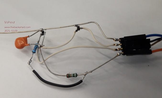 Regards, Volhout Edited 2025-10-09 18:21 by Volhout PicomiteVGA PETSCII ROBOTS |
||||
| Mixtel90 Guru Joined: 05/10/2019 Location: United KingdomPosts: 8911 |
It should be illegal to make mosfets that tiny..... :( Mick Zilog Inside! nascom.info for Nascom & Gemini Preliminary MMBasic docs & my PCB designs |
||||
| Grogster Admin Group Joined: 31/12/2012 Location: New ZealandPosts: 9975 |
@ Volhout: Excellent, thanks. I was pretty sure you would have tested it before publishing the circuit, but some circuits are posted as "In theory, this should work" kind of thing, so I just wanted to be sure. I will get some PCB's made with my next order, and if anyone is interested in these, respond here, and I will start a new thread, with reference to this thread, with the Gerbers etc, so people can get their own ones made if they want. In the public release, I will remove my www reference on the bottom silkscreen. Edited 2025-10-10 07:40 by Grogster Smoke makes things work. When the smoke gets out, it stops! |
||||
| lizby Guru Joined: 17/05/2016 Location: United StatesPosts: 3784 |
Any progress to report on this watchdog PCB? Following with interest. PicoMite, Armmite F4, SensorKits, MMBasic Hardware, Games, etc. on FOTS |
||||
| Grogster Admin Group Joined: 31/12/2012 Location: New ZealandPosts: 9975 |
Yes, I have them, I just have to build one to play with, and take some photos and upload them here. Yesterday in NZ, we had a major storm that caused huge amounts of damage and cut power in a plethora of places, and I have been resetting systems and settling down upset things that have lost their power for the last day or so, but I hope to get a chance to build one of these this weekend. Smoke makes things work. When the smoke gets out, it stops! |
||||
| Grogster Admin Group Joined: 31/12/2012 Location: New ZealandPosts: 9975 |
Assembled one, but have not tested it yet. Hopefully over the weekend.  Smoke makes things work. When the smoke gets out, it stops! |
||||
| The Back Shed's forum code is written, and hosted, in Australia. | © JAQ Software 2026 |
