Notice. New forum software under development. It's going to miss a few functions and look a bit ugly for a while, but I'm working on it full time now as the old forum was too unstable. Couple days, all good. If you notice any issues, please contact me.
poida Guru Joined: 02/02/2017 Location: AustraliaPosts: 1515
Posted: 09:37am 24 Oct 2026
Copy link to clipboard
Print this post
I have good code now. it was not good when I suddenly enabled it with a huge DC offset. it did not settle, it wildly oscillated.
so I added a bit of a "settle down you PID thing" thing. for the first 250 1/2 waveforms at 50 Hz, it runs the bang/bang control, to get it close enough for jazz, than it switches over to PID.
it works really well now. very robust no matter what you do. switch in a DC load? no problemo mate switch on the DC control logic? no matter if there is or is not any DC imbalance it just works.
I will not publish this code here. yet. Edited 2026-10-24 19:38 by poidawronger than a phone book full of wrong phone numbers
analog8484 Senior Member Joined: 11/11/2021 Location: United StatesPosts: 254
Posted: 05:40pm 24 Oct 2026
Copy link to clipboard
Print this post
Looking at the code snippet in an earlier post, the integral gain is 0 while the derivative gain is non-zero. This seems to be the opposite of the original/standard nanoverter PID params? In general, it seems risky to use non-zero derivative gain for an inverter especially given the large startup surge scenarios like what KeepIS sees in his system.
The proposed correction limits make sense at least as guardrails in development testing.
Testing with more challenging but still realistic load conditions (e.g. microwave oven and half-power hair dryer running at the same time) would help verify real world control stability.
poida Guru Joined: 02/02/2017 Location: AustraliaPosts: 1515
Posted: 10:48pm 24 Oct 2026
Copy link to clipboard
Print this post
yes, I will leave the testing in real world conditions up to others.wronger than a phone book full of wrong phone numbers
wiseguy Guru Joined: 21/06/2018 Location: AustraliaPosts: 1338
Posted: 12:14am 25 Oct 2026
Copy link to clipboard
Print this post
Congratulations on your achievements to date and thanks for your efforts. Maybe you are planning to do a longer post to describe the methodology cause I'm sure others here would love to know more too. And a laymans description (for those of us code challenged) would be an excellent help. What are the extra bits and potential hardware modifications that will be needed to implement the "fix" as it currently stands & do we have to reassign an existing analog function pin?If at first you dont succeed, I suggest you avoid sky diving.... Cheers Mike
poida Guru Joined: 02/02/2017 Location: AustraliaPosts: 1515
Posted: 04:18am 25 Oct 2026
Copy link to clipboard
Print this post
Mike, I think we can use the nano Pin A7 for this. I suspect you did not use it in your designwronger than a phone book full of wrong phone numbers
poida Guru Joined: 02/02/2017 Location: AustraliaPosts: 1515
Posted: 04:25am 25 Oct 2026
Copy link to clipboard
Print this post
Here is what I have done.
I use a test inverter that does not have huge DC bus capacitance which reduces the risk of destruction. Capacitance is 6,600 uF. Test inverter uses a 1.5kW toroid and primary winding voltage is only 21V AC RMS for the 54V DC supply. When running PWM width is only about 460 clocks of the 795 clock width maximum when outputting 240V AC. I doubt the above is critical to the performance of the DC imbalance scheme.
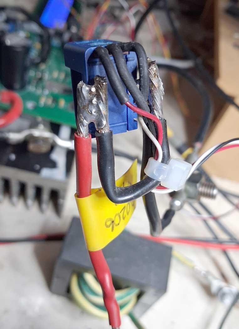
Only one extra component is needed. A modified LEM CASR 15-NP current sensor. It has 4 pins, 5V, GND, OUT and REL I leave REL unconnected. OUT is at 2.5V with zero current passing through the sense wires. I modify the sensor as seen below, to decrease it's sensitivity by putting a shunt on the current sense wires. It is now 0.0206V/Amp I connect the sensor to the Nano's 5V,GND and A7 pins.
The control scheme:
In this discussion I will call the two outputs from the inverter board V1 and V2. We know that we create the AC voltage on the primary winding by alternatively driving V1 from zero to AC peak voltage and back to zero while holding V2 to DC ground. And then we drive V2 from zero to AC peak and back to zero while holding V1 to DC ground. This is how we synthesize the AC waveform.
In my code I maintain a variable that is = 1 when V1 is active It is = 0 when V2 is active. We need this for the control scheme.
When the AC voltage crosses zero, I obtain the primary current from the sensor and store it in either "pc_v1" if V1 is active or store it in "pc_v2" is V2 is active.
if (v1_active == 1) pc_v1 = fabs((float)(analogRead(PRI_SENSE) - 514)) ; // need only absolute value of current at zero crossing else // but must check both times pc_v2 = fabs((float)(analogRead(PRI_SENSE) - 514)) ; // and store the two values
This way I can get information on which output is driving the toroid to saturation. I noticed that the high current from saturation is present at zero crossing and it occurs after the corresponding 1/2 wave was driven by the inverter. If V1 was active, then I saw a large pc_v1 value relative to pc_v2 and if V2 is active, I saw a large pc_v2 relative to pc_v1
I only store the absolute values so current sensor orientation is not important!
(Should the load not be purely resistive there will be a phase delay or lead in the primary current. Let's say it's leading and so I expect (with zero evidence to support myself) that the Voltage zero crossing instants will have currents that are similar in magnitude but opposite signs. if all is well, no DC imbalance such that the toroid will saturate. I think my scheme will work with reactive loading of significant percentages too. I can't test this, I need a small AC motor or something.)
I then run one of two closed loop controls which provide for changing the main output variable called "i_balance". This variable can move between strict limits, in my case of from -0.1 to +0.1 This is more than enough for testing with loads up to 400W with or without the diode in series.
The simple closed loop control is "bang-bang" and is easy to work out.
if (pc_v1 > pc_v2) i_balance -= 0.001; if (pc_v1 < pc_v2) i_balance += 0.001;
what it means is i_balance will slowly move more negative if the current when V1 is active is larger than the current when V2 is active. And conversely, i_balance will move more positive if V2 current is greater than V1.
I then check if i_balance is within safe limits (+/- 0.1) and then modify the corresponding inverter output voltage to suit.
what this does is it combines both the DC balance control and the AC output voltage control in one statement.
Firstly, notice I calculate pwm amplitude maximum values for the 2 half waves and not simply calculate a single value used for both V1 and V2 as in ALL PAST FIRMWARE.
if i_balance is > 0 i.e. positive, it means V1 was getting into saturation and so we need to reduce it's amplitude. This is done by multiplying the amplitude by (1.0 - i_balance) which will be something smaller than 1.0 and so it will reduce the amplitude. Which is what we need.
if i_balance < 0 i.e. negative that means V2 is getting into saturation to some degree and so we need to reduce V2 amplitude. Since i_balance is negative I use (1.0 + i_balance) as the expression.
That is all bang-bang control is, pretty simple to do. It does not even need to know the actual values of the two current measurements, it only needs to know which one is larger than the other.
Of course we need some changes in the interrupt code to use the now 2 seperate max. pwm values for V1 and V2 output. It looks like this now.
if (v1_active == 1) { c = (l[pcount] * vpwr_v1) >> 16; OCR1B = c; } else { c = (l[pcount] * vpwr_v2) >> 16; OCR1A = c; }
This way I can modify one or the other 1/2 wave output voltage independently from the other which is needed for this scheme to work.
I implement a soft start for the DC balance control, for the first 2.5 seconds I let the bang-bang control bring things back to near DC current balance at zero crossings then I switch over to PID. We now use the values of the current measurements to calculate correction factor to add to i_balance. once bang-bang is complete, I now run this code instead of the b-b code:
Setpoint[1] = 0.0; Input[1] = pc_v1 - pc_v2; // where the magic happens. do_pid(1); i_balance = i_balance + Output[1];
I define the desired setpoint, we want zero imbalance of the two zero crossing current values I feed the PID control what is happening, which is pc_v1 - pc_v2, i.e. the AC current imbalance then I run the PID code and get the result which is added to i_balance
and then the same limit testing of i_blance before I modify the required 1/2 wave amplitude as seen above.
Because I now need 2 PID controls, I modified the code to work with 2 sets of values for the two control loops, one being the AC output voltage and the other the new DC balance loop.
From trial and error, I found I need rather small values of P and D for the DC balance loop. This is likely due to my code using A-D converter counts as the working values in the variables pc_v1 and pc_v2. Roughly there are 4 counts per Amp when the sensor output is converted. Edited 2026-10-25 19:00 by poidawronger than a phone book full of wrong phone numbers
wiseguy Guru Joined: 21/06/2018 Location: AustraliaPosts: 1338
Posted: 01:16pm 25 Oct 2026
Copy link to clipboard
Print this post
Thanks for taking the trouble to explain what it's up to, I was able to follow the scheme - but relating it to the code statements & what the Nano is up to deep down will take me somewhat longer.
I like the LEM current transducer shunted shunt or desensitisation link - it is actually a very valid method I have also used for an ACS715 SMD and I just used some wide 2oz PCB trace to shunt the ~60% of the current away from the sensor, temperature drift did not really affect its calibration too badly either.
With the code you have created and if I understand you correctly it does not care much about polarity or magnitude I think it will lend itself to ease of experimenting and optimising for larger and more difficult loads. Maybe magnitudes could play a part later for bigger loads and larger adjustments may need to happen more quickly.
I am now enthused to clear up the various Tesla coils, Audio amplifiers and other crap cluttering my bench that I've been playing with lately and wipe the dust off my inverter and finish adding the second stage. Meanwhile I will make another single stage test bed inverter for ease of playing scoping measuring tweaking testing code etc. I did have one but it went walkabout and never came back.... Edited 2026-10-25 23:17 by wiseguyIf at first you dont succeed, I suggest you avoid sky diving.... Cheers Mike
analog8484 Senior Member Joined: 11/11/2021 Location: United StatesPosts: 254
Posted: 05:33pm 25 Oct 2026
Copy link to clipboard
Print this post
Thanks for the great overview of the enhanced control scheme. Will it be possible to change the current sensor without changing code? The LEM sensor is nice but it seems limited in capacity even with the shunt (~100A limit?). I wonder if the DC current sensor (600A limit?) KeepIS uses in his inverter could be used. I imagine the sensitivity/resolution won't be nearly as good as the LEM sensor. But that may be good enough except for perhaps situations like the idle hum imbalance?
wiseguy Guru Joined: 21/06/2018 Location: AustraliaPosts: 1338
Posted: 12:19am 26 Oct 2026
Copy link to clipboard
Print this post
I have been thinking (uh oh...) about your scheme and some experiments I would eventually like to try, but first can you comment on feasibility please?
Now that you are controlling both halves of the sinewave, that opens up a Pandoras box of control things that can be experimented with. Such as monitoring/adjusting the peak voltage of each half sinewave, on the fly even?
I previously said that we would need to measure for at least 360 -540 degrees before making any adjustment, but if we make limited gain adjustments for each 180° it would catch full wave and halfwave loads.
So let's assume we just turned on the hairdryer, first load driven 180°, primary peak is slightly reduced, take a note (during the 180° non drive) to increase the drive for the next 180° load cycle.
In this manner we only went half a cycle towards saturation before balancing the drive again. Once we have had a chance to play and learn maybe we could slightly over drive the following driven cycle by the same amount we under drove it on the previous loaded half cycle to quickly bring the magnetics back to the same (or closer) condition we had before the load was applied? Note this would require code.
In theory if we measure the 2 x 180° (primary) peaks decide which peak was larger and use that to feed A7 we could get a similar control for the voltage condition - if external sample and holds were used to satisfy your read at zero crossing maybe the code also would not need changing just to try this scheme out?
This is not to suggest your scheme is not the best way to drive the beast, but I will always wonder until I prove that it doesn't or can't work, whether we can stop or minimise Toroid saturation, maybe even before there is a detectable current increase?
Maybe the voltage method could be integrated with the current condition too for belts and braces. Please don't go buy copius alcohol etc this is just thinking out loud not asking for code.... If at first you dont succeed, I suggest you avoid sky diving.... Cheers Mike
poida Guru Joined: 02/02/2017 Location: AustraliaPosts: 1515
Posted: 01:50am 26 Oct 2026
Copy link to clipboard
Print this post
Mike, maybe something in these thoughts of yours re. separate control of each 1/2 cycle. I need to let this sink in for a day or two.
analog8484: I'm certain we will find suitable current sensor signal range when the time comes. I just use what I have in the open box 'o junk on the bench without any prior calculations or thought. I'm familiar with the LEM sensors, their signal range is limited to 2.5V +/- 2.2V sort of and when the current exceeds the capability of the sensor's output, it becomes very clear to see on the DSO
First I want to remind us all that the toroid I use in testing, along with ALL the other inverters I have built, is rated at 240V AC RMS on one of it's secondary windings. This winding is what we use for the AC output. When 240V AC RMS is seen on this winding, the toroid core is starting to show signs it is moving into some degree of saturation. (a few people here have charted AC voltage verses inverter DC current and the curve rises very quickly as we we get to 240V and go higher.)
Once you accept the usual running condition of the inverter is not much at all saturation but give it a bit more and it will saturate some more, it is clear to me even small current imbalances will lead to clear signs some saturation is happening.
Always I have seen primary winding current spikes when the core is saturated to any significant degree. See one thing and the other thing is there. I say this to reinforce my view that primary current is a very good telltale of what is happening to the toroid and since it's easy to sense I like using it.
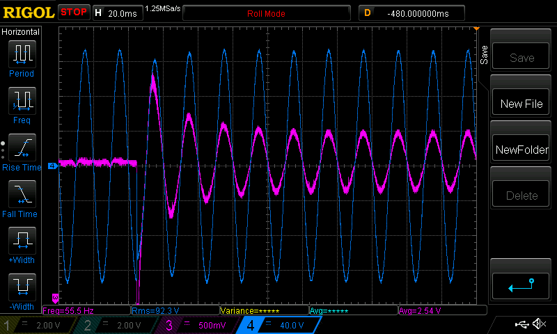
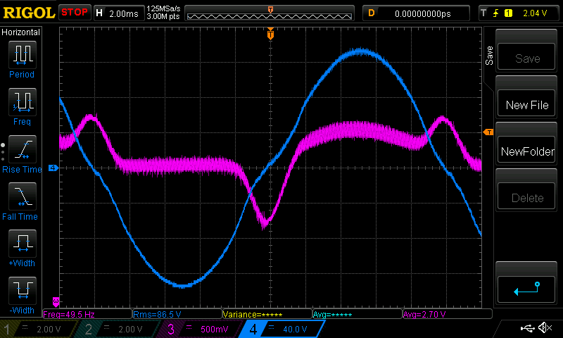
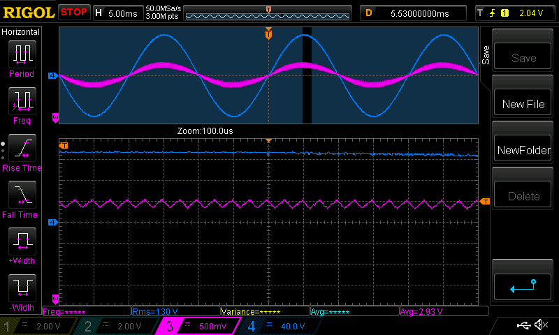
Here are some more results. First is showing how quickly my test scheme responds to switch on of a load.
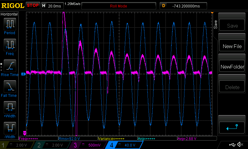
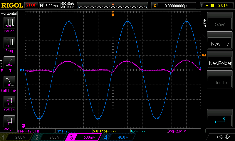
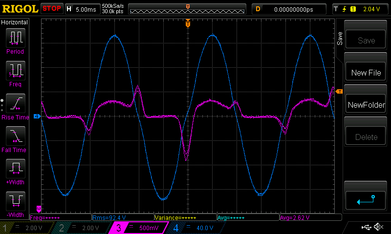
Dark Blue is AC output, taken from the spare secondary winding on the toroid. It will not show the voltage seen by the lights after the diode stops one half wave. Purple is primary current.
This is when I switch in 300W
now I switch in the 300W load with diode. How will the DC balance control work?
not bad. it eventually after a second or two settles to not having the little negative current blip any more and I can't show this on this time scale.
Here is the "normal" good result of the dc balance control with the unbalanced load. looks good.
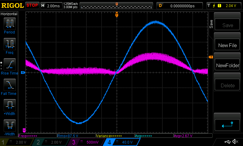
I wanted to upset the test setup somehow and it was easy as a matter of fact. I added another 1.5kW toroid, connecting it's 240V secondary to the inverter 240V output - at the same location I apply all loads. When you leave it's primary unconnected it is now an inductor. here it is now.
not so good. a bit noisy too. The control scheme is doing it's job and it has settled to a state where there are equal current magnitudes at zero crossing but things seem quite wrong. These current magnitudes are quite large. compare these with the ones above. the peaks are about 1.4 divisions or about 40 Amps.
So it's clear my code needs some further work.wronger than a phone book full of wrong phone numbers
wiseguy Guru Joined: 21/06/2018 Location: AustraliaPosts: 1338
Posted: 02:49am 26 Oct 2026
Copy link to clipboard
Print this post
Peter, that was a surprising result with just the second toroid connected to the AC output. The last picture is telling us something - but maybe in a foreign language...
I'm not sure of your LEM current measurement, filtering of it etc but is it possible the <> check is actually seeing it as balanced albeit for a visually unbalanced crappy waveform ? ie it sees the 2 saturation peaks are ~ the same level ignoring the non-zero upper current waveform in-between?
I really like the 2 independent loops, you can see the mains level dip and then be restored all within ~ 1 - 2 cycles, meanwhile the internal tweaks are busy going about reducing the saturation spikes, almost transparently as far as the mains output looks.
I appreciate the time and effort you have put in to explore a situation that has not really caused anyone grief yet, but yet it would be very nice to tame it a bit more if we can.
Oh and re the half wave corrections there would need to be a limit set somewhere between unloaded and fully loaded peaks, tweaking to drive (to adjust) harder than the fully loaded example when trying to balance the peaks does not sound like the best plan, at that point it might be better to accept a slightly reduced AC output by reducing the other 180° drive until balanced. As I said a Pandoras box of worms lol Edited 2026-10-26 13:02 by wiseguyIf at first you dont succeed, I suggest you avoid sky diving.... Cheers Mike
poida Guru Joined: 02/02/2017 Location: AustraliaPosts: 1515
Posted: 04:56am 26 Oct 2026
Copy link to clipboard
Print this post
Mike, it's not noise, it's the nice linear current behavior when the choke is charged and discharged from the pwm 54V we hit it. It is nice to see but you and I like to work with the average current.
I would like to filter this out and I just did now with a good combination of capture settings for the DSO. 30K mem depth, high res mode, display 100ms persistence, vectors
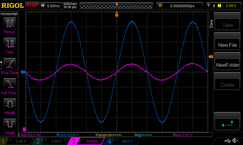
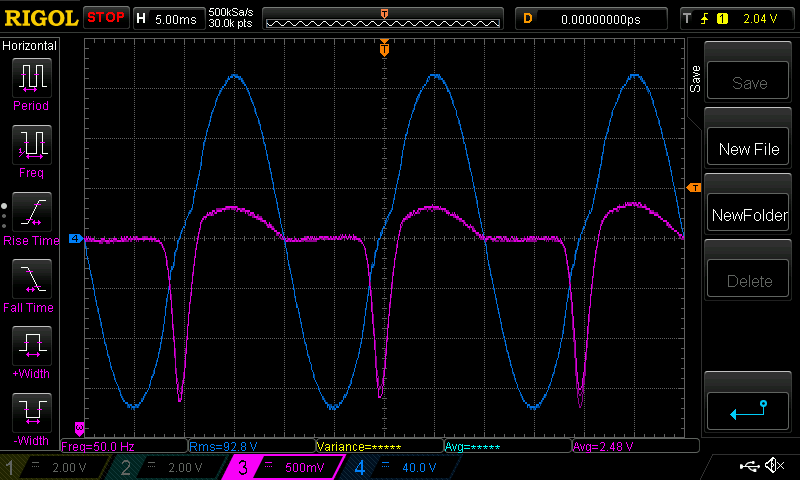
so here are the tests I did before with the better settings for the current sensor trace.
200W AC load, no dc balance control
200W DC load, no dc balance control
same but with dc balance control active
200W dc load, 1.5kW toroid on load, dc balance control not a nice result at all.
wronger than a phone book full of wrong phone numbers
wiseguy Guru Joined: 21/06/2018 Location: AustraliaPosts: 1338
Posted: 05:09am 26 Oct 2026
Copy link to clipboard
Print this post
Haha my description of crappy waveform was taken too literally, I was looking at it from an A/Ds perspective of trying to measure something that is other than a smooth level or waveform. It was really a great waveform capture not at all crappy to me.
I know what the sawtooth is from and why its there, but to your credit, you have posted some lovely smooth waveform pictures - but I actually prefer to see everything warts and all going forward, I will try to keep in mind flippant language that may cause extra work to be done.... the images you first posted in my mind were actually very similar to the later lovely waveforms. edit: Actually I can work with either, the latest pictures are great but I fear without the sawtooth etc it could lead you astray if you forget what is actually there.
The curious part to me was the positive going saturation at the end of the driven half wave, that was my comment about the peaks being even/balanced as far as your tweaker goes, so despite the saturation events at the 180° zero crossings it did not try to adjust anything to reduce the saturation events. Edited 2026-10-28 17:28 by wiseguyIf at first you dont succeed, I suggest you avoid sky diving.... Cheers Mike
wiseguy Guru Joined: 21/06/2018 Location: AustraliaPosts: 1338
Posted: 07:38am 28 Oct 2026
Copy link to clipboard
Print this post
Peter if you still have the same setup, when you added together the DC load and the mains winding of the second Toroid, is it possible your circuit worked just fine?
As there is an almost pure inductive load the circulating current at 90° to the voltage being returned to the source might be causing the second peak that looks like saturation?
Did you try to drive that half wave and inductive load with the balancer off, it may have showed some of that new saturation looking peak? Also if you have a few mains rated capacitors somewhere between 0.5uF and 10uF (Im guessing 1 to 4u7 would do it, you might be able to shrink that spike resembling saturation by just placing a capacitor across the winding with an opposite XC to the toroids XL to cancel that peak?
It has been bugging me how it seemed to be saturating on the driven side yet it was usually the undriven side that tended towards saturation. Edited 2026-10-28 17:40 by wiseguyIf at first you dont succeed, I suggest you avoid sky diving.... Cheers Mike
analog8484 Senior Member Joined: 11/11/2021 Location: United StatesPosts: 254
Posted: 07:10pm 31 Oct 2026
Copy link to clipboard
Print this post
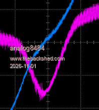
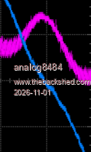
This is an interesting test with the high current pulses around the zero crossings due to the magnetizing current in the transformer load. If you look at the pulses, you can see each pulse is basically balanced with active and reactive components that are roughly equal hence very little real power is consumed. If the inverter control has already reduced the AC voltage output to the minimum acceptable level then I doubt the inverter control can do much more to further reduce the pulse peaks.
It's an example of the limitation that I mentioned before where it's not always possible for the inverter to compensate 100% for large load disturbances while still generate acceptable AC voltage level. In such situations, if the remaining current pulse peaks after inverter compensation are still too large for too long then perhaps the inverter should do a soft ramp shutdown? It's kinda of an overload condition.
Another aspect of the test results that I want to point out is the AC voltage waveform distortions around zero crossings caused by the current pulses (see images below) where the active component of the current pulse pulls the voltage magnitude down while reactive component pushes the voltage magnitude up.
This is a very mild example of distortions but is illustrative of the much more severe distortions caused by aggressive anti-islanding disturbance injections from grid-tied inverters around zero crossings that I have observed. Aggressive anti-islanding disturbances can be much larger and have unbalanced active/reactive components that effectively change the AC voltage zero crossings/frequency if the inverter does not compensate fast enough.
The zero crossing region is especially a weak point for slow control loop (i.e. half mains cycle or slower control update rate) inverters because the nominal SPWM drive is normally quite low there. So, ultimately I believe faster (~1ms or faster) control updates at least around zero crossings are necessary to compensate for more challenging disturbances. Edited 2026-11-01 05:12 by analog8484
johansen Newbie Joined: 01/08/2014 Location: United StatesPosts: 17
Posted: 12:38am 01 Nov 2026
Copy link to clipboard
Print this post
So it seems to me you cant have it both ways.
Reducing the voltage delivered to the transformer on the unloaded half wave, to compensate for the voltage drop in the inverter and copper primary, produced equal flux density each half of the waveforms in the inverter transformer.
But the voltage on the output of the inverter is not balanced due to the voltage drop in the 240vac secondary.
So any downstream transformers (particularly high permiability toroids) are subject to be driven to saturation by unbalanced loads.
Godoh Guru Joined: 26/09/2020 Location: AustraliaPosts: 721
Posted: 03:07am 01 Nov 2026
Copy link to clipboard
Print this post
I don't know the reason or if it makes any difference to what you folks are trying to fix but. I pulled my Selectronics inverter cover off a few days back. Something I noticed was that the transformers are not wound all the way around the core. There is quite a gap between the ends of the windings. They do have inductors too, but it may be something we could look at when we wind our transformers. The two I made I wound all the way around. If I ever make another one, ( not sure I will) I may try leaving a gap. Pete
Revlac Guru Joined: 31/12/2016 Location: AustraliaPosts: 1310
Posted: 05:58am 01 Nov 2026
Copy link to clipboard
Print this post
A long time ago I had the heat gun on the transformer-less inverter, there was very little distortion seen in the waveform (could be due to the cheap DSO) however the inverter would shut down due to over voltage on the DC bus. It could be swamped with other electrical loads and the inverter kept running.Cheers Aaron Off The Grid
analog8484 Senior Member Joined: 11/11/2021 Location: United StatesPosts: 254
Posted: 04:51pm 01 Nov 2026
Copy link to clipboard
Print this post
I actually see the unbalanced load compensation mostly working as intended. The unbalanced load doesn't really have much to do with the large but roughly symmetric/balanced current pulses due to the undriven load transformer around zero crossings. They are mostly due to circulating current that happens when transformers are paralleled with a voltage difference. To verify, the unbalanced load could be disconnected and the large current pulses around zero crossings should still happen.
In the test, the load transformer was not driven on the primary side so the secondary voltage difference from the inverter output transformer secondary would be at the max hence the large current pulses. If the load transformer was driven to have exactly the same voltage waveform as the inverter output transformer and synchronized with zero phase difference then the current pulses around zero crossings should be near zero (with active inverter compensation for unbalanced load) as there would be no circulating current between the transformers.
analog8484 Senior Member Joined: 11/11/2021 Location: United StatesPosts: 254
Posted: 04:58pm 01 Nov 2026
Copy link to clipboard
Print this post
Yes, HF inverters don't have to deal with the output transformer saturation issues like LF inverters. I've slowly realized it's one of the very few advantages HF inverters have over LF inverters.
Page 4 of 6
Print this page
The Back Shed's forum code is written, and hosted, in Australia.

 Notice. New forum software under development. It's going to miss a few functions and look a bit ugly for a while, but I'm working on it full time now as the old forum was too unstable. Couple days, all good. If you notice any issues, please contact me.


 Print this post






 however the inverter would shut down due to over voltage on the DC bus.