Notice. New forum software under development. It's going to miss a few functions and look a bit ugly for a while, but I'm working on it full time now as the old forum was too unstable. Couple days, all good. If you notice any issues, please contact me.
Frank N. Furter Guru Joined: 28/05/2012 Location: GermanyPosts: 1199
Posted: 08:02pm 15 Nov 2026
Copy link to clipboard
Print this post
Okay, I just couldn't stop thinking about it, so I tried it right away:
The output is always 4026531840 (both before and after calling the file manager).
...but when I typed “FILES ”B:“”, the LED went out right away!!! What does that tell me now?
Frank
phil99 Guru Joined: 11/02/2018 Location: AustraliaPosts: 3453
Posted: 08:43pm 15 Nov 2026
Copy link to clipboard
Print this post
Check for a short or leakage between GP21 and GP22.
Mixtel90 Guru Joined: 05/10/2019 Location: United KingdomPosts: 9379
Posted: 09:08pm 15 Nov 2026
Copy link to clipboard
Print this post
Part of the problem is that you have to use COM2. You should rule that out, no matter which pins it's on. COM2 is reserved and on GP8/GP9 by default in MMBasic. Olimex have given you no choice other than to ignore those pins and the MAX chip while you are looking for the problem. You need access to COM1 and, ideally, to isolate GP8/GP9.
The Olimex board was never designed to be able to work with MMBasic. MMBasic is being moulded to fit, but there could be unforeseen nasties lurking which don't occur on a MMBasic platform. I have similar problems with my own boards - they are not "official" MMBasic platforms.Mick
phil99 Guru Joined: 11/02/2018 Location: AustraliaPosts: 3453
Posted: 09:56pm 15 Nov 2026
Copy link to clipboard
Print this post
The console can be moved to COM1 or disabled if not needed.
Edited 2026-11-16 07:59 by phil99
mozzie Guru Joined: 15/06/2020 Location: AustraliaPosts: 524
Posted: 04:24am 16 Nov 2026
Copy link to clipboard
Print this post
G'day, Frank, can you please advise what revision of chip you are using (A2?), I have an RP2350A0A2 setup on a breadboard here with the same Option List as yours and cannot replicate what you are seeing with regards to opening the file manager changing the pin status. Something very odd going on...
On startup the pins not defined have the internal PULL-DOWN enabled, this could be enough to light your LED and cause the MAX3232 to output a continuous start condition on the RS232 TX line. A 4K7 pullup to 3V3 on GP20 (TX) should overcome the pulldown and solve the problem. I have needed to do this in the past.
Mick, the serial console on COM2 (GP8/GP9) is only used on some (USB) variants and can be moved to other pins if neccesary, I have needed to do this in a few cases. If there is something wrong with COM2 being used for other purposes we need to figure it out, a problem will come and "bite me on the ass" at some point for certain.
Regards, Lyle.
Mixtel90 Guru Joined: 05/10/2019 Location: United KingdomPosts: 9379
Posted: 08:14am 16 Nov 2026
Copy link to clipboard
Print this post
Exactly my point. If the problem goes away when COM1 is used and COM2 is ignored then there is a deeper problem. If the problem is still there then the problem is external to the firmware/Pico hardware. If testing for that means moving the Pico to a breadboard then so be it. You can't run a valid test if the Olimex hardware might be getting in the way.
According to the RP2350 Datasheet GPIO pins are set to high impedance at reset. Is setting up a COM port enabling the pull down then? Pull up and pull down resistors are around 30K-100K so you don't get much current through them at 3V3.Mick
matherp Guru Joined: 11/12/2012 Location: United KingdomPosts: 12251
Posted: 08:19am 16 Nov 2026
Copy link to clipboard
Print this post
Frank
Is this the board that a Pico plugs into? If so, please try and get a Pico or compatible with an RP2350 with A4 stepping rather than A2. I'm beginning to suspect this is the E9 raising its head.
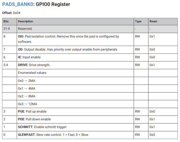
Your PEEKs are invalid. All four read 4026531840 = &HF0000000. The registers can't hold that value, and it's what I'd expect from boot ROM word 0, so I think your address evaluated to 0 (a dropped &, or a variable name). ? PEEK(WORD 0) on any RP2350 would confirm it. Typed correctly, the prompt should show 22 for both pad registers and 31 for both CTRL registers.
To do list:
Wiring: which UEXT pins your MAX3232 board uses. It should be only 1, 2, 3 and 4. Short check: with the power off, measure resistance from UEXT pin 8 to pins 3 and 4. Voltages: measure UEXT pin 8 and his LED line after power-on and again after FILES "B:". They should move together. Without a meter: run OPTION SDCARD DISABLE and power-cycle. GP7 is then held only by the weak pull-down instead of driven low, so the LED should be faint at power-on, not bright. Edited 2026-11-16 18:34 by matherp
ville56 Guru Joined: 08/06/2022 Location: AustriaPosts: 680
Posted: 09:26am 16 Nov 2026
Copy link to clipboard
Print this post
tried it on A2 stepping (Pimoroni pico plus 2), IMHO no problems. The behaviour is as follows:
after reboot: all pins are pulled low via pulldown resistor
dout: after setpin gp20, dout pin is pulled active low pin(gp20) = 0 or 1, pin is pulled active low or high pin(gp20)=off, pin is pulled low again via pulldown resistor
setpin for com2: after setpin gp20,gp21,com2 the pins are pulled high TX is pulled active high RX is pulled high via pullup resistor
open "com2: 300" as #1 does not change the pin states (TX active high=idle=space, RX high via pullup) print #1, string$(100,"A") actively toggles TX pin, RX stays high via pullup
so far that is working as expected. I suppose the pull to low via pulldown on reboot is to prevent charge buildup on unconnected pins which makes sense to me.
tried on A4 as well. Results are exactly the same Edited 2026-11-16 19:36 by ville56 73 de OE1HGA, Gerald
Mixtel90 Guru Joined: 05/10/2019 Location: United KingdomPosts: 9379
Posted: 09:46am 16 Nov 2026
Copy link to clipboard
Print this post
Interesting... This isn't in line with the official (and huge) Datasheet that I have for the RP2350. I can only assume that it's part of MMBasic. The Datasheet is quite specific, the input buffer is disabled and the totem pole output devices are switched off, leaving the pin as high impedance. This may have changed in a later revision or errata, but it's not the sort of thing that usually does.Mick
ville56 Guru Joined: 08/06/2022 Location: AustriaPosts: 680
Posted: 11:31am 16 Nov 2026
Copy link to clipboard
Print this post
I'm surprised too:
from the RP2350 datasheet:
9.3. Reset State At first power up, Bank 0 IOs (GPIOs 0 through 29 in the QFN-60 package, and GPIOs 0 through 47 in the QFN-80 package) assume the following state: • Output buffer is high-impedance • Input buffer is disabled • Pulled low • Isolation latches are set to latched (Section 9.7) The pad output disable bit (GPIO0.OD) for each pad is clear at reset, but the IO muxing is reset to the null function, which ensures that the output buffer is high-impedance.
So it should be high impedance after reset, but is not.
The strange thing for me is that if the pin is set to input, the pin state is high impedance and it changes to pulldown as soon as the reset button is pressed (and not yet released). So this is noting the firmware does handle, is suppose.
EDIT: and another effect I don't understand but not related to the silicon: e.g. Pico RP2040, RC9
after reboot GP0 is pulled low via pulldown, so far so good. setpin gp0, dout GP0 is active low, OK
LIST PINS gives for GP0 GP0 1 DOUT
but issuing setpin gp0, ain Error : Invalid configuration is OK, this is not possible but
the pin is not driven active low anymore, it seems to be in hi-z state. This seems to be a bug in the MMBAsic firmware.
LIST PINS gives still GP0 1 DOUT
but the state is now different. pin(GP0) = 0 does not drive the pin to active low anymore but leaves the pulldown on. pin(GP0) = 1 seems to activate the pullup but does not drive the pin to active high.
can be recovered with setpin gp0, off setpin gp0, dout
Maybe this is something for Peter to have a look at. Edited 2026-11-16 22:29 by ville56 73 de OE1HGA, Gerald
mozzie Guru Joined: 15/06/2020 Location: AustraliaPosts: 524
Posted: 01:17pm 16 Nov 2026
Copy link to clipboard
Print this post
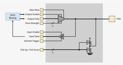
G'day, A look at the GPIO/PAD circuit in the datasheet shows the PULL-UP/PULL-DOWN as connected directly to the pad itself, so will be active regardless of any other settings of the pad / gpio registers:
This assumes as usual I haven't missed anything
I still maintain a 4K7 pullup to 3v3 on GP20 will solve at least part of the problem by over-riding the pull-down current. The issue with the FM or files command is still a mystery, possibly a faulty board or chip?
Among the most stressful experiences one can have in one's career as a designer is connecting two serial devices. I don't mean a terminal and a modem - such a connection is child's play - but any other connection can mean real difficulties. For example, every time I buy new equipment it goes like this. I spend five minutes reading the brochure, five minutes paying for it, and five hours trying to figure out how to get the new device to communicate with my computer.
— ”Ciarcia’s Circuit Cellar” , BYTE, april 1983.
Mixtel90 Guru Joined: 05/10/2019 Location: United KingdomPosts: 9379
Posted: 02:36pm 16 Nov 2026
Copy link to clipboard
Print this post
Things haven't changed much since 1983 have they? :)
RS-232 has been a headache since its conception. You can never have enough standards. xkcdMick
ville56 Guru Joined: 08/06/2022 Location: AustriaPosts: 680
Posted: 03:36pm 16 Nov 2026
Copy link to clipboard
Print this post
Yep, had to connect all kind of test- and manufacturing equipment and a barcode system via RS-232/RS-485 scattered all over a 10000 m2 shopfloor to PDPs and VAXen in the 1980 and 1990ies. And ethernet was too new for the equipment suppliers. Was fun, sometimes at least. 73 de OE1HGA, Gerald
ville56 Guru Joined: 08/06/2022 Location: AustriaPosts: 680
Posted: 03:42pm 16 Nov 2026
Copy link to clipboard
Print this post
Don't quite understand this. If the PAD is set to input neither PULLUP nor PULLDOWN can be active. IMHO they are controlled individually (see the /2 marker in the control line). Same applies for output settings of course. But I may be wrong as usually. 73 de OE1HGA, Gerald
mozzie Guru Joined: 15/06/2020 Location: AustraliaPosts: 524
Posted: 04:14pm 16 Nov 2026
Copy link to clipboard
Print this post
G'day Ville56, The /2 does indeed indicate 2 control bits and PULL-UP and PULL-DOWN can be controlled individually, but the control bits are separate from the input enable / output enable so they can be active at any time, and are not affected by the PAD ISOLATION register AFAIK
Regards, Lyle.
Frank N. Furter Guru Joined: 28/05/2012 Location: GermanyPosts: 1199
Posted: 06:56pm 16 Nov 2026
Copy link to clipboard
Print this post
@Peter: - This is my board: https://www.olimex.com/Products/RaspberryPi/PICO/RP2040-PICO-PC/open-source-hardware - Unfortunately, I only have the RP2350 with Revision A2 here. - SORRY! I had misunderstood you. Here are the results before and after FM (the results are identical both before and after):
- Yes, only pins 1, 2, 3, and 4 are connected. - There is no connection between 8 and 3/4. - Upon reboot, Pin 8 is at GND; after FILES "B:”, Pin 8 is at 2.47 V. - With OPTION SDCARD DISABLE, the LED turns off immediately; with OPTION SDCARD GP22, GP6, GP7, GP4, it turns back on
@phil99: - I measure 565 kOhm between GP21 and GP22
@mozzie: - I haven't tried the 4K7 pull-up to 3V3 on GP20 (TX) yet.
Frank
matherp Guru Joined: 11/12/2012 Location: United KingdomPosts: 12251
Posted: 07:55pm 16 Nov 2026
Copy link to clipboard
Print this post
Frank
Thanks, that narrows it down a lot. The LED and the COM problem are the same thing. The LED lights when your RX line (GP21) is low, and when you drove GP21 high it only dimmed, so something outside the Pico is pulling that line low. A UART whose RX is held low receives nothing but a continuous break, which is why the HX-20 reports errors. FM only fixes it because it mounts the SD card.
Your PEEKs show GP20 and GP21 are in exactly the same state before and after FM: pull-down on, input off, no function selected. The firmware isn't doing anything different to those pins.
What does change is the SD card's MOSI line, GP7, which is UEXT pin 8. With OPTION SDCARD set, GP7 is driven low from boot until the card is first used, and is high after that. With OPTION SDCARD DISABLE nothing drives it, and the 10k pull-up on the Olimex board holds it high. Your LED is on exactly when GP7 is low. Your 2.47 V on pin 8 also suggests something is pulling current out of GP7; with nothing but the card and that pull-up on it, it should read about 3.3 V.
According to Olimex's schematic for the board, GP20 and GP21 go only to UEXT pins 3 and 4, and GP7 goes only to the SD card, UEXT pin 8 and that pull-up. There's nothing on the board connecting them. So the connection must be in the MAX3232 board, its wiring, or the cable. An ohmmeter with the power off won't find a path that goes through a chip.
First, please confirm one thing: after power-on, type FILES "B:" (no FM) and then RUN your program. Does it talk to the HX-20?
Then, to confirm the cause without the SD card code involved:
OPTION SDCARD DISABLE The board restarts and the LED should be off. Then:
SETPIN GP7, DOUT PIN(GP7) = 0 PIN(GP7) = 1 If the LED comes on at 0 and goes off at 1, it's GP7. Then repeat with the SD card taken out, and again unplugging the four wires to the MAX3232 board one at a time, to find the path. Afterwards put the card back with OPTION SDCARD GP22, GP6, GP7, GP4.
Until it's found, your program should run without FM if its first line touches the card before COM2 is opened:
IF MM.INFO(EXISTS DIR "B:/") THEN : ENDIF That mounts the card, which leaves GP7 high, and doesn't change the current drive.
The workaround line hasn't been run on a board. I checked in the code that it mounts the card and keeps the current drive.
mozzie Guru Joined: 15/06/2020 Location: AustraliaPosts: 524
Posted: 02:59am 17 Nov 2026
Copy link to clipboard
Print this post
G'day Frank, The 4K7 pull-up on GP20 will stop a continuous break condition being sent on the RS232 TX to the HX-20 before you open the COM port in MMBasic.
Some devices ignore this break condition however many take it as a reset or similar and respond in a variety of different ways.
Hopefully with this and sorting out GP21/GP22 your project will be successful
Regards, Lyle.
Frank N. Furter Guru Joined: 28/05/2012 Location: GermanyPosts: 1199
Posted: 05:47pm 17 Nov 2026
Copy link to clipboard
Print this post
@Peter:
Unfortunately, it can't be the MAX3232 board. It wasn't connected at the time of the measurement. I took the measurement directly from the UEXT without a cable. I also tried two MAX3232 boards and two Pico 2s. The behavior was the same every time.
I'll try that out later.
The moment I enter SETPIN GP7, DOUT, the LED turns on. There is no change when PIN(GP7) = 0. When PIN(GP7) = 1, it turns off.
Sorry, but I don't understand what I'm supposed to do: When I remove the SD card, the system behaves the same way. When I enter OPTION SDCARD GP22, GP6, GP7, GP4, I get the error message: “Error: Pin 10/GP7 is in use.”
After a reboot, the LED stays off until I enter OPTION SDCARD GP22, GP6, GP7, or GP4. The LED then turns back on immediately (even if no card is inserted).
IF MM.INFO(EXISTS DIR “B:/”) THEN : ENDIF seems to work. The LED turns off immediately. I'll try adding that line to my program and see if communication with the HX-20 works then.
@mozzie: Thank you very much! I don't have any resistors available right now, but I plan to give it a try.

 Notice. New forum software under development. It's going to miss a few functions and look a bit ugly for a while, but I'm working on it full time now as the old forum was too unstable. Couple days, all good. If you notice any issues, please contact me.


 Print this post