
|
|
Forum Index : Windmills : I finally got an F&P where to now?
| Author | Message | ||||
JimBo911 Senior Member Joined: 26/03/2009 Location: United StatesPosts: 262 |
First off my mill is not facing the wind directly (just like Phills was per his Getting It Right post)during regular winds. It wants to turn away and then back in to the winds left to right etc. I have to change the tail so the mill will face into the winds. It's furling way to early, but when the high winds hit it hard the tail jumped up and sat there about half to 3/4 furled MAN it was cranking Wooooooo. YEAH it's spooky for sure watching the blades disappear. My women and I were grinding our teeth there for awhile. No vibration or shaking to speak of. Time will tell. Jim |
||||
| GWatPE Senior Member Joined: 01/09/2006 Location: AustraliaPosts: 2127 |
Hi Karl, surprises me to. I think my wooden blades are heavy at 700g each for a 3m rotor dia. The main thing is that they work well and will perform the job for many, many years. Gordon. become more energy aware |
||||
| KarlJ Guru Joined: 19/05/2008 Location: AustraliaPosts: 1178 |
nice work Jimbo, you must be proud. Gordon... just to clarify the 4130g is each blade ..... making a rotating mass of at least 13KG. Wood obviously has some advantages in the weight dept! Luck favours the well prepared |
||||
| KarlJ Guru Joined: 19/05/2008 Location: AustraliaPosts: 1178 |
I couldn't help myself, this seems to be the std tail arrangement, it got cleaned up last night so I straightened it and put it to use. 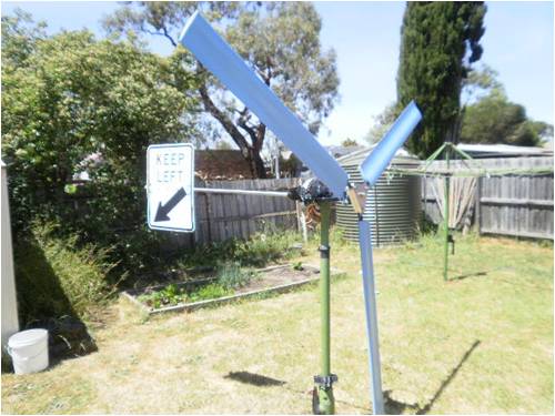
now I need a keep right for the other side balance is now with 1g of each other and the CofG on each blade in exactly the same place, thus should be balanced. Luck favours the well prepared |
||||
| KarlJ Guru Joined: 19/05/2008 Location: AustraliaPosts: 1178 |
Next up the tower.... I have abandoned the idea of using an old windmill tower at roughly 7m high on the grounds that steel is cheaper than life and working on the top of one of these would be quite dangerous. New solution as follows. Steel as follows 100mm SHS 4mm thick wall x3 lengths 6m long. Solution bury two of them in the ground 100mm apart 2m deep in a 600mm diameterx2000mm deep hole full of concrete. place the third in between with 3.5m below the top of the other 2 poles this leaves 2.5m above the two fixed towers, weld in 50mm pipe to the top section a further 1.7m attach turbine. this gives a total height of 8.2m hinged at a little less than 4m from the top, enabling tilting over in a pendulum type manner. use a large bolt to attach the tilting part top and bottom. this should be plently big enough what are your opinions? no guy wires would be used. Luck favours the well prepared |
||||
Downwind Guru Joined: 09/09/2009 Location: AustraliaPosts: 2333 |
Phew! Hope you have a good long handle shovel? 2m deep is a long way down, it might not sound much till you look down the hole or have to drill it. At 600 dia x 2m is almost 0.6 m3 of concrete per hole. That�s a lot. ( around $100.00 per hole) I would think 1 m x 2 holes would be plenty. (unless you are in a swamp) Power poles are not even 2m deep and without concrete. The other thing I would suggest would be weld a plate to the top of the steel coming out of the concrete and bolt the above ground structure to it. Should you need to remove the tower or do a redesign in the future you can without a mass structure sticking out of concrete for ever more. If you weld up the basic mount for above ground and bolt it to the in ground pieces prior to setting concrete than all can be levelled and setup before concrete is poured. Once set unbolt the frame and finish construction of the tower and then secure to base footings again afterwards. I have seen many footings mounted on large threaded bolts where a nut is placed under and ontop of the plate so the structure can be adjusted for level by adjusting the nuts up and down. Have a look at some of the highway street light mountings as often they use a simular system. Should you do 2m holes and strike oil than retire. Pete. Sometimes it just works |
||||
| KarlJ Guru Joined: 19/05/2008 Location: AustraliaPosts: 1178 |
Here's the sketch 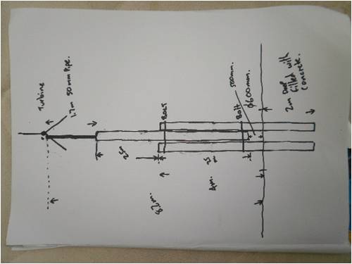
digging the hole is a piece of cake, dad is building a shed too and a guy comes out with a bobcat and auger, will take about 10mins. As you suggest upgrade later will not mean new foundations. the 0.6m3 of concrete which I work out to be 2400Kg/m3 = roughly 1400KG. There would only be one hole as combined width is only 300mm. If you reckon 300mm and 1m deep is enough then I have a post hole digger on the tractor that will do this no worries. similarly if 1 pole either side is overkill then could use a single pole and use f&p shaft for the pivot. this simplifies the installation / cost significantly. Luck favours the well prepared |
||||
| KarlJ Guru Joined: 19/05/2008 Location: AustraliaPosts: 1178 |
This is tower option 2(lightweight version) 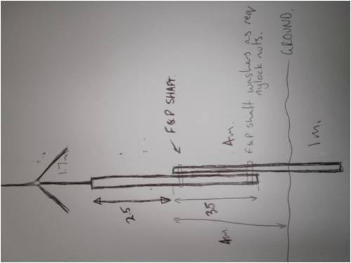
diameter of the hole in this case would be 400mm and only 1+ m deep (ie use the post hole digger I have and enlarge a little. Karl Luck favours the well prepared |
||||
| Downwind Guru Joined: 09/09/2009 Location: AustraliaPosts: 2333 |
Karl, If you are in good digging and can go deeper than it might be worth while. I misunderstood and thought the footings were further apart. I think a metre would do but if you can get a bit more it wont hurt. A few things I think a smart bloke like your self would know but will point them out all the same. Ensure the concrete is covering the bottom of the steel as this where the rust sets in and causes early failure if the steel protrudes outside the concrete. As the bottom end is now sealed in concrete you will need to cap the tops off to keep water out and would pay to weld in a tube sleave for the axle to go through or water will find its way in there to. (Maybe drill a small hole at ground level after to allow moisture to escape should it get in) I would think use option #1 with 2 uprights and you wont be sorry you did as a short cut here will be something you are stuck with later. You might get away with 1 box section into the ground and then 2 sections either side with a metre over lap. The little saving might not be worth it as the greatest force will be at ground level. Weld the two uprights together with a spacer between them before setting into concrete as it will be a bugger of a job to align them otherwise. A tip I used when setting rhs into concrete for large retaining walls ( big steel) is to use 2 lengths of timber to span the hole and bolt the timber together sandwiching the steel in between so the steel can then be lifted off the bottom with a couple of bricks under the timber to ensure the concrete covers the bottom of the steel. I would look towards a hand boat/trailer winch to lower and raise the pivoting section, they are about $30.00 at supercheap autos and would think should give nice control and be $ well spent. Perhaps remove the winch when not needed. If it was me I would consider 2 lengths of C section into the ground ( flat side inwards) and the box section for the tilting mask. This way there is nowhere to collect water and be as strong if not stronger and easier to work with. Pete. Sometimes it just works |
||||
| KarlJ Guru Joined: 19/05/2008 Location: AustraliaPosts: 1178 |
yes I though the C section would be easier as you dont need to weld a pipe inside the square section to deal with compressive forces caused by doing up the bolt, also means I can use the F&P shaft, cut splines off both ends and tap a thread into it, use bolt with washer, spring washer and loctite. Thats the go then we'll price that up tomorrow. Cheers Luck favours the well prepared |
||||
fillm Guru Joined: 10/02/2007 Location: AustraliaPosts: 730 |
I would recomend pricing in some guy wires as close to the blade dia as well. PhillM ...Oz Wind Engineering..Wind Turbine Kits 500W - 5000W ~ F&P Dual Kits ~ GOE222Blades- Voltage Control Parts ------- Tower kits |
||||
| KarlJ Guru Joined: 19/05/2008 Location: AustraliaPosts: 1178 |
cant have guy wires, have cattle which will do damage to them and the tower...... could 4mm wall 100mm SHS really move?, its bloody heavy stuff! BTW I have decided that wind turbines, wiring, electronics are all fairly straightforward, the tower is a serious piece of engineering that unlike the turbine, you really only get one shot at. Luck favours the well prepared |
||||
| Downwind Guru Joined: 09/09/2009 Location: AustraliaPosts: 2333 |
Hmmmmm Cattle?? Them buggers will wreck anything not fenced in. I bet the wiring will not last a week before it is chewed up.(seen the buggers eat the taillights out of the ute while fixing their trough, the greatful sods) The mongrels have a tongue 3 feet long when it gets near plastic coated wires. Thats if they dont rub and rub your mill down first, then proceed to trample over it and crap on anything important. Best advice is while the proline is on the tractor to drill the footing hole stick down 4 post holes and fence the mill in. Maybe use the posts as anchors for some guide wire for extra support. When the mill is tilted over it may reach outside the fenced area, just dont leave it and go for lunch as the blades might be shorter when you return. They are kind critters like that. Take the advice and design the destructive buggers out. I love cattle in every way, steak, roast, sausages. Pete. Sometimes it just works |
||||
| KarlJ Guru Joined: 19/05/2008 Location: AustraliaPosts: 1178 |
sounds like a good idea, give the mill a 2mx2m, gives you some working space use some 100mm gal steel posts at 3m long with a link of chain welded to it for a guy wire anchor, put them 1m in the ground with some concrete and lay them outward ie not vertical from the mill. Luck favours the well prepared |
||||
| JimBo911 Senior Member Joined: 26/03/2009 Location: United StatesPosts: 262 |
Karl I thought that I would add my two cents in about your tower or support structure, again just my thoughts. I have been in the construction industry my entire working life or lets say 35 years. I have helped set everything from 300 cubic yard concrete footers for tower cranes to 2 inch fence posts. I have been an self employed earth excavator for 15 years not bragging just telling what I do for a living. You said that building the mill/electronics is one thing but the tower is another and you are correct. Normally guys wires are used and the concrete base (foundation) is basically supporting the weight of the tower so most of the lateral support comes from the wires. If you do not plan to use guy wires then the entire structure has to be supported by the foundation alone. Not sure if you have seen any foundation footers or bases for self supporting towers but I will tell you they have to be big, heavy and some of them deep. Of course it all depends on the structure your trying to support. Firstly you have to know what type of soil conditions your planning to place footers in to ie. hard clay, sandy clay, rocky loose soil, blue clay, how much top soil etc. Hard undisturbed, clean, clay in it's natural state is best. If it was my call(with no wires)I would forget about your light single pole design. A 1 meter deep concrete pier would be a BAD thing. I do not know where your frost line is but here it's 4 feet deep. If you don't get down below your frost line I don't care how big (wide) the footers are the freeze thaw cycle will push the pier out of the ground or shift it around it's just a matter of time. Hell I don't even know if the ground freezes there but it is something to consider if it does. I would opt for your heavier design. It just so happens that I own three Bobcats and just about every attachment that they make for them. If it where my call I would have your Bobcat man bring out (or rent) a 30 inch to 3'foot dia auger with the three foot extension with this arrangement he will be able to auger down approximately 7 to 8 feet i,ve done this many times so when he says it can't be done you tell him HOG WASH, hopefully there will be no large rocks. Yeah I know this sounds like an over kill but it's not. DO NOT set the pipes or what ever your going to use in the concrete this will weaken the pier and dose not allow you to level, adjust, plumb or mess around with your tower, set bolts in the concrete then bolt on your tower to the pier, this will also give you a way plumb it straight. Going with a 3'pier will allow you to go higher and or with a larger tower in the future that is after you build your 3kw mill. My mill seems to be balanced well I can not see any rotational vibration at all but I do see lateral thrusting when the wind hits the blades and when the wind dies off quickly. The tower has to be relatively stiff so the spinning blades do not get a chance to respond to an oscillating tower. Make it strong if you have any unanswered questions then make it stronger the survivability your of your mill depends on it. My mill sits on top of a 6 foot deep 18 inch dia concrete pier when I disconnect all the wires to lower it down I can see the pier moving yes it does move when tilling because the pier at this time not only holds the weight but also supporting the pivoting action. Anyways just my two cents. Jim |
||||
| KarlJ Guru Joined: 19/05/2008 Location: AustraliaPosts: 1178 |
I have good clay, close to the surface (tower is basically on a wind swept hill, hence erosion of the topsoil) I have no frost whatsoever. not setting the pipes into the concrete means some kind of cage made of reo bar with the bolts welded to it..... this could be interesting, could I just weld a flange on the pipe at this point sink the pipe to avoid building a cage? Karl Luck favours the well prepared |
||||
| JimBo911 Senior Member Joined: 26/03/2009 Location: United StatesPosts: 262 |
Karl That's good news all clay in a winded area. You don't really have to build a cage you can buy bolts from a building supply house/contractors supply. 3/4 foundation bolts about 1 foot long they will come with a 90 degree bend on one end this will be the end that you muck in the concrete. Figure out your bolt pattern then use a piece of 1/2 or 3/4 plywood or any piece of wood that will match your bolt pattern. Drill holes in the plywood that match your bolt pattern then use the nuts and washers that come with the bolts to fasten them to the plywood this will hold the bolts in place while you just muck or place the hooked end in the wet concrete. You can then use a spirit (bubble) level to level the plywood this will plumb the bolts at the same time. I would have about 4 to 5 inches of bolt extending above the concrete. I have used what we call a sona tube to extend the concrete pier above the existing grade elevation. The tubes come in different sizes. It's all very simple stuff. 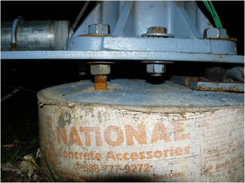
Jim |
||||
| Downwind Guru Joined: 09/09/2009 Location: AustraliaPosts: 2333 |
Karl, I do agree with Jim and it is a standard building practice here to and is what i was leading towards in a earlier post. ( about making it bolt down ) The only thing i question is no steel down into the footing. ALL concrete cracks and i have never seen or constructed a footing that has not called for steel reo almost full length (normally 100mm shorter) of any footing. The reo rod can be cut lengths pushed into the concrete after the pour and not needed to be in a cage. It would be bad luck if the footing cracked just under the bolts used, and you end up with a floating footing on top of a concrete block. The reo should over lap the depth of the bolts and in some cases the specs have called for a bend to be placed in some reo and hook over the L in the bottom of the bolts. ( in a lot of location this would need to be certified even for a flag pole at this height ) The reo is cheap and the method you choose im sure will be well thought through before you do it. AS Jim has mentioned the in ground movement of the footing with tower loading, I wonder if it is worth trenching a cross ( X )about a meter out each side of centre and also filling it with concrete and some reo place in it to, so as to give a bigger foot print at ground level ( sort of a in ground out riggers ) The best thing about bolting it down is if you get a leaning tower of pisa with time then you can adjust it. Pete. Sometimes it just works |
||||
| JimBo911 Senior Member Joined: 26/03/2009 Location: United StatesPosts: 262 |
Pete You are correct reo is good. The cross is an excellent idea as well, kinda like spread footing, more footing less movement. Jim |
||||
| KarlJ Guru Joined: 19/05/2008 Location: AustraliaPosts: 1178 |
is that 6mm plate under the tower? Luck favours the well prepared |
||||
| The Back Shed's forum code is written, and hosted, in Australia. | © JAQ Software 2026 |
