
|
|
Forum Index : Windmills : - NEW ALUMINIUM BLADES -
| Author | Message | ||||
| Perry Senior Member Joined: 19/11/2009 Location: Posts: 190 |
Thanks guys. Hopefully some will find it useful. I did spend some time on it. It was actually pretty fun. I was surprised once I started crunching the numbers how high some of the forces get. If there is significant interest I would be willing to work on the next two installments, thrust forces, then gyroscopics. Then we can try to add them all together. Steven, I could use some help on the gyro effects. Can you point me in the direction of some eq's or papers I can research? I think since we have defined the basic model we could get through them pretty quickly. Perry |
||||
| turnymf Regular Member Joined: 04/10/2008 Location: AustraliaPosts: 84 |
Interesting lecture on angular momentum/gyros http://www.youtube.com/watch?v=zLy0IQT8ssk&feature=PlayList& p=F688ECB2FF119649&index=24 |
||||
| dsmith1427 Newbie Joined: 21/07/2009 Location: United StatesPosts: 5 |
Thanks Perry! Nice work on the radial loads. The only thing that I would add is when the blade is pointing toward the ground, gravity is another load (Mass * 9.8). Gravity's contribution is small (39.2 N for a 4kg blade) and is probably negliable but it is still part of the system. Also, does the loading from the wind onto the blades need to be taken into consideration? If we assume a tip speed ratio of seven and RPMs of 1000, the wind velocity is 28.4 m/sec (63 miles per hour). I came up with these numbers working backwards from the following formula. RPM = (Velocity x Tip Speed Ratio x 60)/(2 x Pi x Radius) Won't the wind striking the blade cause loading which is transferred into rotational movement. I am thinking this loading is a linear momentum problem. Do we think this should be evaluated? For those interested in technical aspects of this project, MIT offers the video lectures of it's physics classes (classical mechanics) at the following website: http://ocw.mit.edu/OcwWeb/Physics/8-01Physics-IFall1999/Vide oLectures/index.htm They are free! The professor integrates lectures and demonstrations. Also, you can watch the classes on youtube through a link on the website. Angular momentum is lectures 20 and 21. Don |
||||
| Perry Senior Member Joined: 19/11/2009 Location: Posts: 190 |
Hi Don, Yes you are correct about the gravitational force. I negated it as you have pointed out, it is quite small in comparison. You are also right about the thrust forces. I have yet to add them. These will manifest themselves as bending moments in the support tube. Your formula above is correct and actually provides the airspeed component that is part of the thrust equation. Perry. |
||||
fillm Guru Joined: 10/02/2007 Location: AustraliaPosts: 730 |
Hi Perry & Don I would think that gravity would only come into play if one blade was heavier than the other blades . PhillM ...Oz Wind Engineering..Wind Turbine Kits 500W - 5000W ~ F&P Dual Kits ~ GOE222Blades- Voltage Control Parts ------- Tower kits |
||||
KarlJ Guru Joined: 19/05/2008 Location: AustraliaPosts: 1178 |
I found this courtesy of a link on the tab for aluminium blades. http://www.royalfabrication.com/performance.htm Quote Example: Our test machine is a 3 phase AC alternator with an 18' foot diameter 3 - blade set up. The load resistance measures about 5 ohms. The accompaning voltage graph shows voltage at 20 mph is 70 volts. 70 volts divided by 5 ohms = 14 amps. 70 volts x 14 amps = 980 watts. We multiply this by 3 because of the 3 phases and we get 2940 watts. 1 HP = 747 watts 2940 watts divided by 747watts/hp = 3.9 Horse power 3.9 hp x 550 ft-lbs/hp =2145 ft-lbs of torque about the wind genertor axis. To calculate the mechanical load on the blade you pick an average at about 2/3 distance out on the blade. So a 9 foot blade you would use 6 feet as a lever arm length. 2145 ft-lbs divided by 3 blades = 715 ft-lbs per blade. 715 ft-lbs divided by 6 feet = 119 lbs force on each blade in the direction of rotation. 119 lbs x 3 blades is 357 lbs total rotational force. There is a lot going on up there. Quote end looks to me like torque loading is insignificant next to gyroscopic forces but its still 50KG!!!! on a 9' blade and admittedly here we're ONLY talking abut tiny 5' blades here but the maths they have done might enable someone to use the formulas. Personally, I'm inclined to worry more about my tower! Luck favours the well prepared |
||||
Downwind Guru Joined: 09/09/2009 Location: AustraliaPosts: 2333 |
Heres a new argument on blade mounting to throw into the mixing pot. So far we have been trying to design flex out of the blade system and when all considered perhaps we should design flex into the system. This would allow for the flex to be controlled to a chosen area. Take the springs in your car for instance they are designed in to take loading and permit flex or movement to prevent fatigue in other areas, with out them the chassis would crack up, not to mention the ride. Consider an early model car radiator fan it had a flat metal hub to allow for flex in the blades, same design used on large v16 cat motors up to 6� dia. As Karl mentioned Horsepower!!, Rad fans have mass horsepower applied through them and are designed to allow flex accordingly. Basically rigidity and movement tears things apart and when it stops flexing it breaks. If movement or flex is allowed and controlled up near the hub end, then the blade would be subject to much less fatigue and a greater reduction in blade weight could be achieved. Many of fibreglass blades don�t have a heavy rod or tube up the centre and handle the loadings. Another thought would be to apply a light layer of fibreglass over the blade for strength and fatigue reduction. If a blade was subjected to 50kg of load (I doubt it) than the pvc blades would break in the first wind gust. We can mount a pvc blade from the hub with bolts and no metal rod support up the guts, then why cant the ally be mounted simular as long as the loading is allowed to flex other than in the blade metal itself. Here is a photo of a commercial mill in high winds and have a look at the bend in the blades, if they were made rigid the blades would break in this sort of wind loadings. 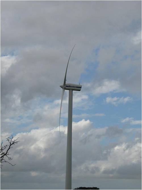
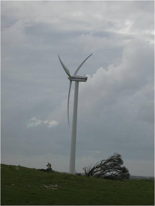
Pete. Sometimes it just works |
||||
| KarlJ Guru Joined: 19/05/2008 Location: AustraliaPosts: 1178 |
Flexing and survive ability is all down to good load transitions and materials that dont mind it. ie mild steel. stainless, aluminium and titanium are all materials that crack and break when subjected to repeated flexing. mild steel flexed upto a point prior to permanent deformation will continue this behavior for a long time in comparison, it will work harden but not nearly to the extent that stainless and aly do. dont get me wrong but the blades in the pics above DO like anything subjected to these kind of loads have a finite life. Being experienced with working on high speed aluminium tubing (aeroplanes) all of my life I was once dumbfounded to find that a Shrike Turbocommander (about 10 seats and two 800+ Hp engines) has a cycle life of just 10,000. Each flight involves pressurising and de-pressurising the airframe, this causes it to grow. It was not until I worked on one that had 9999 cycles and the pressurisation system had been disabled so it could continue in service did I really understand why... It was riddled with cracks, all the rivet holes, lap joints highly loaded areas were stuffed. Luck favours the well prepared |
||||
| Downwind Guru Joined: 09/09/2009 Location: AustraliaPosts: 2333 |
Some interesting stuff you have been involved in Karl. The thought in blade mounting that come to mind is on the lines of what you implied, being a spring steel mounting plate between the blade and hub. The plate could consist of several thiner plates stacked on top of each other to adjust the amount of flex to suit the blade length and weight. Spring steel is some what predictable, allowing for adjustment and less blade fatigue. So design them out and put the force in a material that can handle it. Steel. But the steel needs to flex before the blade. Pete. Sometimes it just works |
||||
| KarlJ Guru Joined: 19/05/2008 Location: AustraliaPosts: 1178 |
I got it............. Blade tube solution FOUND!!!!!!!!!!!!!!!!!!!! found some carbon fiber mast (broken unfortunately into 3m lenghts) in hard rubbish, informed me these are available. check these puppies out http://www.carbonfibretube.co.nz/index.php?pr=Carbon_Tube_Pr ices i'd go for this ID OD price/m weight/m 22 25.6 $ 49.42 0.21 part no RCT 1822 or RCT1522 at $44/m now they are expensive BUT at 210g per metre this just knocked out a chunk of blade weight. Process is cut carbon shaft to 90-100% of blade length -will not protrude outside the blade. Steel round bar 22mm to the hub and into the blade 20" odd. load transition area bore a 3/16 hole into the round bar at least 6" of ever increasing sizes until you are down to a 1mm wall thickness at the end of the solid bar. bond tube to the steel round bar bond it into the aluminium blade for insurance (all major aircraft manufacturers have "jesus bolts") and add a couple of through and through bolts to the carbon steel aluminium joints 1/4" torqued to 35"/lbs (this wont break the carbon) add 6x 1/4 stainless rivets to the aluminium blade / tube as per normal. now some finer points, drilling into carbon requires solid carbide drills or a resharpen every 3 holes. high speed is best 6000rpm. Fibre breakout on the exit side wouldn't be too bad for this material as its pre-preg (small tows). Wet install the rivets with sealant. paint blade with (green) zinc chromate paint (available from any aircraft supplier) then paint as normal. weigh and balance, marvel at the wonder of carbon fibre and watch gleefully as the blades happily do 1000rpm all day every day cracking out 2.5KW into your AX-FX. BTW Pete with 1.5m length blades the 22mm round bar probably will flex. Can I make my own CF tube is the next question I hear.... Answer in short no....would be very difficult. 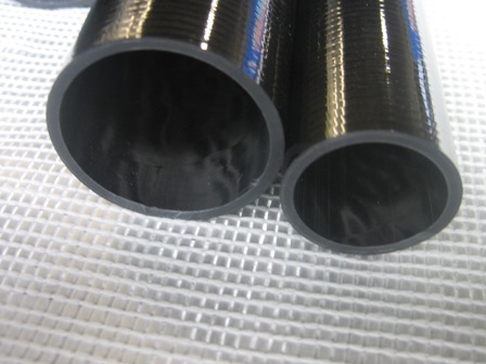
Thinking Phill would have no trouble working out the claming of the 22mm round bar. ALL up starting to look like $100 /m for the blades BUT... where else can you buy something of this quality? ~$450 all up for a set of blades 3m diameter, seems alot but in the grand scheme of a windmill i'm thinking it would be cheap. in fact this solution with 4m blades starts looking possible this would obviously be cheaper http://www.trade.cn/view_selloffer_12689.html but looks like min order 100 pieces and Luck favours the well prepared |
||||
| Downwind Guru Joined: 09/09/2009 Location: AustraliaPosts: 2333 |
I agree with the weight reduction. Think Gizmo sergested CF or fiberglass several posts back. wouldnt putting a CF skin over the blade be about the same as the rod/tube up the guts. I think the last lot of CF mat i bought was around $40.00 per lineal metre. At 210g/m for the tube is pretty good. Another question- what happens if the blade is held under compression? How would this effect metal fatigue? Pete. Sometimes it just works |
||||
| Tinker Guru Joined: 07/11/2007 Location: AustraliaPosts: 1904 |
Karl, you *really* don't want carbon fiber material in contact with aluminium. Its a bad combination, just look up the galvanic corrosion tables. You *definitely* don't want to drill holes through the aluminium blade and into the carbon fiber tube to insert pop rivets  . .
Now, if the blades were carbon fiber you'd get away with stainless hardware.... Klaus |
||||
| Tinker Guru Joined: 07/11/2007 Location: AustraliaPosts: 1904 |
Pete, as I mentioned above, CF & aluminium is a bad combination. Also, when placing a fiberglass or CF skin over plastic or alu blades you have to consider their different thermal expansion rates. If there is a mismatch they will delaminate in time. Klaus |
||||
| Perry Senior Member Joined: 19/11/2009 Location: Posts: 190 |
You seem very confident in this solution. What is that based on? If you calculate out just the centrifugal forces you will see that we are already at 1/3 of the tensile strength for the CF tubes. Add in bending and gyro forces and you will be right up to yield stresses and above before too long. It's true that the CF tubes are strong for their weight but their tensile strength is only 65 ksi. Barely stronger than the proposed aluminum. Yes they are lighter which helps but the mass of the blade itself becomes domineering. CF matrix has the problem that it is relatively brittle as well. So when you have thermal expansion or cyclic bending of the components you will see cracks. Also, carbon fiber has well established design constraints that need to be observed. You can't drill it, lathe it, etc. and expect it to perform as desired. CF works best as a monolithic structure with a full resin preg. Perry |
||||
| KarlJ Guru Joined: 19/05/2008 Location: AustraliaPosts: 1178 |
Corrosion issue with parts next to aluminium is solved with bonding it in and painting the parts first. Similarly all Aircraft parts are riveted together with Jo bolts which although are titanium, stainless would suffice -hence wet install your fasteners to keep galvanic corrosion to a minimum. (would be no worse than steel) Also sealing the ends of the composite is beneficial as the carbon will soak up moisture (tiny but enough) this is done with epoxy. Sorry Perry I disagree -as we've seen in the figures bending and gyro forces are small in comparison with the gyroscopic forces and at only 1/3 of the tensile strength being used up at 1000rpm, they are at least 50% under its maximum loading. I have never seen cracks in composite materials and I've been working with them (Boeing & F/A 18 hornets) for 8 years. Delaminations yes but most of this is due to physical damage. You can drill, lathe and machine it if you wish but its hard on cutting tools. Fasteners could be omitted entirely for a better solution but careful selection of adhesive would then be paramount. Which is why A/C manufacturers use fasteners also. Keep in mind the current thinking here is for stainless tube which is no better re corrosion in the aluminium than the CF. I'm beginning to think the extruded PVC is probably a better material for this application anyway. Luck favours the well prepared |
||||
| Perry Senior Member Joined: 19/11/2009 Location: Posts: 190 |
. |
||||
| Perry Senior Member Joined: 19/11/2009 Location: Posts: 190 |
Hello, Second installment on calculations of Phill's proposed design. Last installment we analyzed the centrifugal loads. This time we will calculate the thrust forces and bending moments on the blade. Question - What thrust forces are Phill's blades seeing and what stresses does this create in the SS (or carbon fiber, or steel, or moon rock) tubes. Model -As before the model is defined as Phill has proposed. It is assumed that the thrust force is applied at the center point (center of pressure) of the aluminum blade section. We are also assuming that the blade extrusion does not participate as a structural member. All rigidity is provided by the tub/rod combination. We will calculate the stress in the tube right where the solid rod ends. This is the point that will be subjected to the most bending stresses due to it's thin cross section. 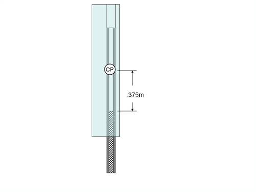
1.) Figure out the thrust force dsmith1427 correctly calculated the wind speed earlier in the thread. Assume TSR of 7. RPM = (Velocity x TSR x 60)/(2 x pi x Radius) This yields 28.4 m/s (63 mph) - pretty close to what Phill observed during his 1000 rpm runaway. You can calculate the thrust force (Ft) from; Ft = 2 x rho x V^2 x a(1-a)x Area Assume the rotor is running at the Betz limit. a=1/3 for this condition. I know that this is not true but it is the best approximation for these calc's. Reducing gives us; Ft = 1/9 x pi x rho x V^2 x Dia^2 for Phill's numbers Ft = (1/9)(3.14)(1.223 kg/m^3)(28.4 m/s)^2 * (3.2 m)^2 = 3524 Newtons Divide this by 3 because we have 3 blades to distribute this thrust force and we see that each blade see's 1175 Newtons or 265 pounds force. Now we can see why that big Vestas turbines' blades were bending. This figure is a bit high but remember that our rotor is operating at the Betz limit, removing %59 percent of the energy in the wind. 2.) Calculate the bending moment in the blade Moment = force x distance (distance is the center of pressure to the point we want to measure) M = (1175N) x (.375m) = 441 N-m Convert it to stress in the tube right where the solid rod ends bending stress = (moment)(tube radius)/moment of inertia Without beleaguering the moment of inertia calc's (not typing in but easy to do) you will see the the MoI (I) is equal to 6.69x10^-9 bending stress = (441 N-m)(.0125 m)/(6.69x10^-9 m^4) bending stress = 823 mpa or about 120 ksi. Ouch. We see that the bending stresses right where the tube ends has already far exceeded the tensile stress of the material. You could always test this if you are stubborn but think about it. Hang a 265 pound weight from a .375m length of this thin walled tube and it will bend. So now we clearly see that the thrust forces contribute substantially to the forces that the tube will see. Since my intent was to combine the models and forces due to bending and centrifugal forces I can finish it up pretty quickly. 3.) Combine forces from each model From my previous post we recall that the stresses due to the centrifugal force on the tube right where the stub ends is 223 MPa. We can combine the stresses according to the following equation 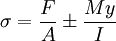
stress = (223 Mpa)+/-(823 MPa) The +/- is due to the front of the tube being in tension and the back in compression So we now know that the tube just outboard of the stub will see 1046 MPa (152ksi)of tension on the upwind side and 600 Mpa (87 ksi)of compression on the downwind side. Summary 1.) Given the design as proposed by Phill we see that by calculating the centrifugal and bending moment forces that the weak point of the design (at the point where the hollow tube begins) will seee tensile stresses of 1046 MPa 2.) This is far beyond the capability of all materials proposed so far, stainless steel or carbon fiber. 3.) I would predict that this configuration would fail given the 1000 rpm criteria given. Hope this helps and no, I am not sh*tting all over your ideas Phill. Just helping out with the math as you have asked. Perry P.S. please check all this over! |
||||
| KarlJ Guru Joined: 19/05/2008 Location: AustraliaPosts: 1178 |
WOW.. now thats an eye opener. moral of the story is no blades should be allowed to go this fast, furling is a must. now dare I ask....what is the safe limit given a fudge factor of 1.3. Assuming mild steel as the material. Karl Luck favours the well prepared |
||||
| Downwind Guru Joined: 09/09/2009 Location: AustraliaPosts: 2333 |
Perry, The forces you quote look to be rather large on the blades. If all blades are loaded to simular forces, than can someone explain how a blade can be cut from a pvc pipe and bolted on by not much more than a flat section onto the hub and dont fly to bits in the first good gust of wind. ( i do realise pvc has a shorter life) I dont question your calculations Perry but question the model you are working with. What would you sergest to lower the applied forces. The heavy ridgid mount up the centre, is that designing the problem in? or is it designing the problem out?? I think the more weight you have outwards away from the hub causes more problems than it solves. The transition from solid to tube looks to be the problem point so why have it inside the blade to start with, as a 22mm dia rod 2-300mm long is not going to allow flex to the blade up to this point and hence creating a fatigue point further out along the blade. It looks that the problem is being designed in and not out. Pete. Sometimes it just works |
||||
| Perry Senior Member Joined: 19/11/2009 Location: Posts: 190 |
Hey Pete, Yes the numbers do seem high but you have to realize that we are talking about an extreme case of turbine runaway. 1000 rpm is a killer for a 3.1m dia turbine. At a 1000 rpm pvc blades this big would shed for sure. Don't question the model because you don't like the results. Let me know what part you think is wrong and why. There is wiggle room in the model. It's a simple model of a first dimensional nature. It is based on classical mechanics and modern rotor design equations though. I could develop a much more accurate one but I am doing this for free. I did assume that Phill's blades worked up near the Betz limit. In fact they won't. But generally the math does not lie. It amazes me when I do some work like this just how high the forces are compared to what I think they should be. So what would I do to improve the situation? Fair question. I think most people are on the right track with trying to keep as much mass as possible off the tips. One could take the calculations I have posted and run a sensitivity study for the best length of stub vs. weight compromises. I think that the very thin wall tubing suggested is a non-starter. The sensitivity study would help to mitigate this. I think that using the blade as a mechanical structure would help substantially. Granted it is not a high strength material but it does have a pretty good cross sectional area. If the tube/rod/blade could be mated together to serve as a single structural component then stresses could be reduced. This assumes we can solve the galvanics, temp expansion, bonding questions first. I just reran the numbers by using a schedule 40 SS tube that runs the entire length of the blade with 125 mm sticking out for attachment. The highest forces this system sees is 267 MPA, a little over half of it's yield strength. So there are tangible solutions here. Perry |
||||
| The Back Shed's forum code is written, and hosted, in Australia. | © JAQ Software 2026 |
