
|
|
Forum Index : Microcontroller and PC projects : External watchdog chips...
| Author | Message | ||||
Grogster Admin Group Joined: 31/12/2012 Location: New ZealandPosts: 9975 |
No, at the moment, it is on the actual input - I will move it. Wait........ Cap moved so it is placed between B of transistor, and deck(ground), and still seems to work the same way, so I will leave it there. 
Cheers - will try that now. Wait...... That works. 
However, with 22k between 555 output, and input, I DO get a singular pulse, but the time delay is now halved on what it was before. At power up, I have about 6s before the first pulse, then subsequent pulses are 3s apart. Still, this is exactly what we need, so we now only need to fine tune the timer from the second cycle onwards. Thanks again, mate! Much better then my transistor switching the 7555 supply idea. 
This half-period from the 2nd cycle may not prove to be an issue anyway, as once the PIC32 has been reset, and so long as the WDT pulses start again BEFORE the 6s timeout, then the time period between resets will still be 6s. QUESTION If the MMBASIC locks up, and the pulses stop, can I assume that the I/O pin used for the pulses, will settle in the low state? I see an issue, in that if the MMBASIC code falls over, if the I/O pin then settles low, the WDT will never trip, as it will stay low, and connecting the 555 cct input permanently low, will stop the timer from timing out, the reset pulse will never happen, and MMBASIC will stay crashed... Pulses are normally positive going anyway via MMBASIC, are they not? Perhaps I need to swap the PNP input transistor for an NPN and swap the collector and emitter connections? I have to go to another job right now, but I will be back to play with this ASAP! Smoke makes things work. When the smoke gets out, it stops! |
||||
| Grogster Admin Group Joined: 31/12/2012 Location: New ZealandPosts: 9975 |
OK folks, I have put the 7555 in place of the 555 and dropped the supply voltage to 3v3. Surprisingly, this did not really effect the time period as I thought it would. Circuit working fine, but I had to drop the 22k on the output pin, back to 10k with the 7555, or it would not pulse the output - it just stayed on like before. This is not an issue really, as thanks to TZA, we are now using the discharge pin as the connection to the PIC32 when the time comes. 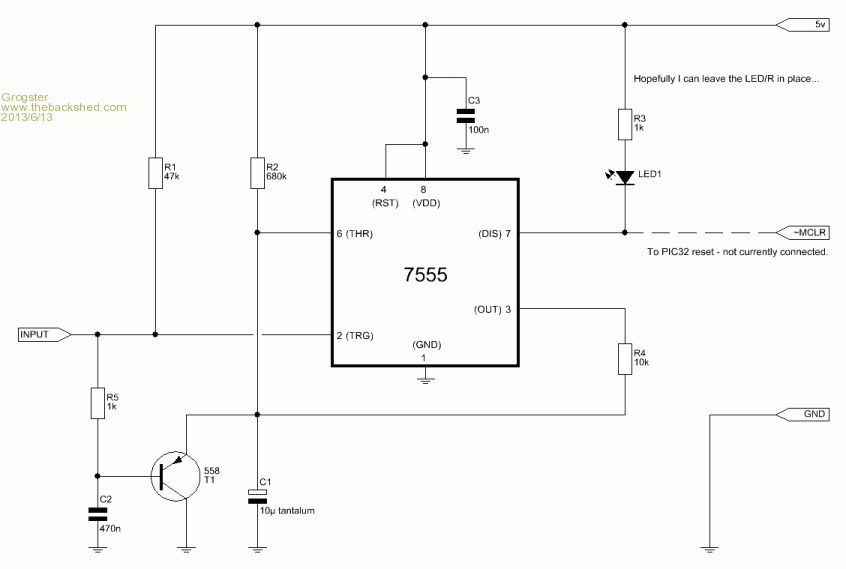
One thing I AM having an issue with, is that once tripped, if you don't pulse the input again within 2s, it starts pulsing again. If I pulse the input again before 2s, THEN wait - the delay is back to 6s or so. This might be something to do with the tolerances between the 555 and the 7555. I think we still need some more tweaking. I will tinker a bit more, and post back with anything exciting. EDIT: Error on the schematic - 680k resistor is actually a 560k. I am about to change this to 680k anyway, but thought I would mention it, as this is the timing resistor, so it will have a bearing on the time period. EDIT: 680k has added about 1s to the 1st cycle time period, but the repeat cycles are still only 2s or so, which is really too short - the MM will not be running again in such a short time from reset. At this point, I am happy for further prods in the design, otherwise we will quit while we are ahead, and I will start playing around with the 6369 WDT chips. It's just they are so tiny... Smoke makes things work. When the smoke gets out, it stops! |
||||
bigmik Guru Joined: 20/06/2011 Location: AustraliaPosts: 2981 |
Groggy, Looking at the above CCT... I suggested the 22k Resistor to go from the 555 output to the trigger input... You have it going to pin 6 (threshold) rather than Pin 2 (Trigger). Is this a change as my suggestion didnt work? I am not surprised the addition of C's and R's affects the timings but that can be overcome by using a Transistor switch... rather than a direct connect. I am also curious... why did you separate the Discharge pin (pin 7) and use that as the output if the cct was basically working previously? This may also have an adverse affect to the original intent of the cct.. If it was me I would try the ORIGINAL cct as referred to by centrex with the addition of the input CAP and feed back trigger (to Pin 2) resistor and see how that goes... Using the 3V 555 Regards, Mick Regards, Mick Mick's uMite Stuff can be found >>> HERE (Kindly hosted by Dontronics) <<< |
||||
| Grogster Admin Group Joined: 31/12/2012 Location: New ZealandPosts: 9975 |
I've made a bo-bo with the cct - yes, 10k(was 22k) comes back to pin2, not pin6 as in the drawing - I will update the drawing... Discharge pin used as "Output" at suggestion of TZA, and it works fine like that. The reason for this, was that the Discharge pin can pull the ~MCLR line low, as it(the ~MCLR pin on the MM) is already pulled high with the 10k pull-up on the MM. If connected to the Output pin, this line is driven-high and driven low, which when driven high, will bypass the 10k on the MM - that may not actually be much of an issue - opinions? I think the discharge pin concept is a good idea, and all of my experiments since TZA suggested that one, have had the test LED connect as in the diagram. However, you have a point - as a final experiment, I will put the LED back on the output pin, but still leave your 22k and transistor cap in place, and see what happens. Corrected circuit: 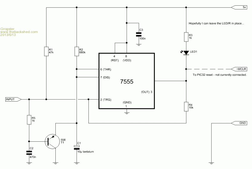
Yes - this does seem to make all the difference. With pin 6 & 7 linked again as in original cct, timings are 6s to first pulse, and 6s for every subsequent pulse - much better. Nice prod, Mick! 
Although, I still liked TZA's idea, but obviously, the 555/7555 was not happy connected like that with respect to the rest of the circuit. I guess that is to be expected, when I think about it... Options now are: 1) Connect 7555 output to PIC32 ~MCLR line, and use the 7555 circuit to directly drive the ~MCLR line high and low when a reset needed - but not sure about bypassing the MM 10k pull-up to the PIC32 ~MCLR like this - please comment. 2) Put another PNP transistor on the output as isolation. E to ~MCLR line, C to deck(ground), and drive it's base from the 7555 output pin. When running, 7555 output will be high, keeping PNP off. When 7555 output goes low with a timeout, PNP pulls PIC32 ~MCLR line low with a pulse, then returns high again. I still have the issue that the pulses from the MM are most likely postive-going pulses, and this circuit needs negative-going pulses to make it work, so I probably need to change the input transistor to NPN type and tinker some more. Smoke makes things work. When the smoke gets out, it stops! |
||||
| Grogster Admin Group Joined: 31/12/2012 Location: New ZealandPosts: 9975 |
OK, here is the new cct: 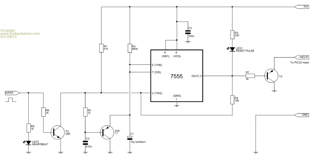
This one uses a simple transistor inverter on the input, so that positive-going pulses can be used to keep the WDT going without playing around with the values of the original cct(lesson learnt!), and also a buffer transistor on the output - isolation is a good thing, IMHO. Yes, it uses extra parts, but 548's and 559's are cheap as chips... Smoke makes things work. When the smoke gets out, it stops! |
||||
| Geoffg Guru Joined: 06/06/2011 Location: AustraliaPosts: 3362 |
This should not be a problem. The 10K was only there to allow MCLR to be driven by a programmer. Geoff Graham - http://geoffg.net |
||||
| Grogster Admin Group Joined: 31/12/2012 Location: New ZealandPosts: 9975 |
Okey dokey.
With a 10uF tantalum cap(C1) and 1M2 resistor(R2) as the RC components, the time period between output pulses is 14s, which is actually about what I wanted, so now, the time has come for me to connect the circuit to the MM and see what happens. I also added a 4u7 cap between pin2 and GND - this provides a slightly longer output pulse(about 250ms). I am guessing that the PIC32 does not need much in the way of a lengthy reset pulse - I will check the datasheet. MCU's certainly have their place, but this good-old timer design was very interesting for me to build up and fault-find with the help of others. It is nice to find a new use for the 555/7555, which I have not used in years and years. 
I will be designing a PCB for this unit very shortly. I will make provision for either a fixed resistor or a variable one. The board will be designed to plug directly into the CG CMM units, but it could naturally be used with any other MM version simply by adding flying leads to the WDT module. If anyone thought it worthwhile, I would upload the PCB gerber files here, so others could also build it if they wanted. Smoke makes things work. When the smoke gets out, it stops! |
||||
| bigmik Guru Joined: 20/06/2011 Location: AustraliaPosts: 2981 |
There would be no affect at all with the MCLR pin being high and the MCLR pullup... The only possible problem would be, if a physical RESET switch was fitted (doesnt seem to be in a standard CMM), then a `hard' GND would be applied to the output of the 555 .... maybe a small value 220R in series with the output of the 555 cct to stop the RESET switch damaging the 555. I agree the cct is now back to how it was intended to work (more or less) No problem with or without the 10k Pullup... leave it in ... no harm.. No need now for an output transistor as you are using a 7555 off 3v3... As for the pulse .... If the pulse command is ONLY positive going then create your own pulse by setting the pin LOW then setting it back to a high state.. or if you specifically want a High going pulse and use the PULSE command simply ADD an extra transistor between the PIC Strobe pin and the input of the 555 to invert the pulse (BC548 NPN would do)... I can provide that cct later but I am at work at the moment and dont have all my resources here... Regards, Mick EDIT*** Sorry I should have read a bit further before replying to you... I missed a couple of MSGs... If you get a run of PCBs I wouldnt mind one or two please... let me know costs.. Mick Mick's uMite Stuff can be found >>> HERE (Kindly hosted by Dontronics) <<< |
||||
| Grogster Admin Group Joined: 31/12/2012 Location: New ZealandPosts: 9975 |
Will do, Mick.
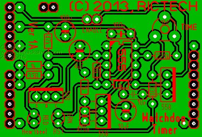
I have designed the prototype PCB, and will etch it over the weekend, if I can find the time. Circuit has jumper on ~MCLR line, so that you can "Enable" the WDT by placing the shunt on the jumper pins, and "Disable" it by removing the jumper shunt - allows for quick testing etc, without risk of the WDT resetting the MM while you are doing something. Also fully adjustable from 3s to 14s time period via on-board trimmer. I will post a photo of it once it is assembled. Here is an image from the PCB software: 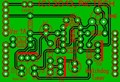
PCB is 53mm x 36mm, and plugs directly into the CG CMM units, where the Sheild footprint is. Smoke makes things work. When the smoke gets out, it stops! |
||||
| Grogster Admin Group Joined: 31/12/2012 Location: New ZealandPosts: 9975 |
Final PCB is ready - I will get some boards made next week at PCB Zone. I added two more caps, and changed one other as per the 555 datasheet etc. ADDED: 100uF decoupling cap on 5v supply, and 10n cap on pin5(CV) of the 555, as per the datasheet recommendation. I checked this on the breadboard, and the 10n on pin5 does not seem to have any effect on the operation of the circuit, and in fact, is recommended when the 555 is used in mono-stable mode like this, so... CHANGED: 10uF tant for a standard aluminum 10uF electro. Reading about tants, it would seem that they intently dislike being shorted out, and that is exactly what the transistor across the cap is doing, so I elected to replace it. When timing is not mission-critical, a "Drifty over time" standard electro should not really pose much of a problem, and it is also a much cheaper cap then a tant. The pin-strips where the Shield socket is, have been replaced with just holes only. This allows the board to suit either male or female pin-strips/sockets, depending on what is on the CG CMM. In MY case, I fitted pin-strips where the Shield socket is, as I thought that would be easier for me to jumper out to breadboards for prototyping etc. In hindsight, I should have put female socket strips on there, as normal. Either way, the holes-only concept allows for either, and means I can use SS PCB's which halves the price of the PCB. (original idea was DS board with plated-through holes just for the Shield footprint, but for the extra pads, I have to pay twice as much for the DS board, so in order to keep the costs down... You slide the WDT board onto the pin-strips on the Shield footprint(in my case), and then use jumper shunts to link from the adjacent pads, to make the connection. Either that, or short solder links. Not exactly the prettiest design, but it is simple, and it works.
Smoke makes things work. When the smoke gets out, it stops! |
||||
| bigmik Guru Joined: 20/06/2011 Location: AustraliaPosts: 2981 |
Hi Groggy, Looks good, Regards, Mick Mick's uMite Stuff can be found >>> HERE (Kindly hosted by Dontronics) <<< |
||||
| Grogster Admin Group Joined: 31/12/2012 Location: New ZealandPosts: 9975 |
PCB Zone make excellent boards, so I expect the finished boards to look the business. They work out at NZ$10 a board(A$8.40), less the parts and assembly, naturally. This is for professional soldermasked, drilled and silkscreened boards - NOT homemade ones. If you(or anyone else) want one, let me know by PM, and I can adjust the order. At this stage, I am getting 5 boards made. Smoke makes things work. When the smoke gets out, it stops! |
||||
| Grogster Admin Group Joined: 31/12/2012 Location: New ZealandPosts: 9975 |
Attached to this post, and as one of the final posts here(I imagine), is the ZIP file which contains the Gerber files(Silkscreen1, Copper2, Soldermask2) and the drilling data in Excellon format. ZIP file also includes a PCB layout image, the circuit schematic(in GIF image format), and a basic description. 2013-06-17_062514_Watchdog_Timer2.zip Thanks to all who offered advise with this.
Smoke makes things work. When the smoke gets out, it stops! |
||||
| Turbo46 Guru Joined: 24/12/2017 Location: AustraliaPosts: 1693 |
I want to use a similar external watchdog circuit in a slave. The slave needs to count the number of restarts and report this to the master. I have come with this: While it works, it counts all restarts which is OK I guess but it would be nice to have only count the restarts caused by the watchdog timer. I could add a latch which is set by the watchdog, then read it's state on startup, then reset the latch but I don't want to go to that complexity. Does anyone have a suggestion. Is there a more elegant way of doing this? Bill Keep safe. Live long and prosper. |
||||
| HankR Senior Member Joined: 02/01/2015 Location: United StatesPosts: 209 |
Bill, You awakened a creature after almost 6 years of hibernation. Could that be a "Microcontroller and PC projects" record? H |
||||
| Turbo46 Guru Joined: 24/12/2017 Location: AustraliaPosts: 1693 |
Could be? I didn't want to start a new topic so I though I would resurrect this one because it's very close to what I want to do. Started well before I joined too! Bill Keep safe. Live long and prosper. |
||||
| Grogster Admin Group Joined: 31/12/2012 Location: New ZealandPosts: 9975 |
@ HankR - Heh, heh!  Yes, this thread was started before Geoff had the Watchdog command in the interpreter. Not long after we perfected this thing, Geoff had a new release with the WATCHDOG command. I am sure he must have been watching us to get his release timing right!   My first thought would be to make use of the MM read-only variable MM.WATCHDOG, which is set to one, if the watchdog has restarted the MCU. However, that only works with the internal watchdog. The way you are doing it is about as simple as it gets. You could always throw a one-wire UNIO memory chip(11AA160 or 11AA161) on your project and connect a spare I/O to that, and record those sorts of things in it, as they have a claimed 1,000,000 write cycles and you would then not need to worry about wearing out the internal flash on the MM chip. They cost about 50c each, and Geoff has written a Cfunction to make talking to them a breeze. Smoke makes things work. When the smoke gets out, it stops! |
||||
| Turbo46 Guru Joined: 24/12/2017 Location: AustraliaPosts: 1693 |
Thanks Grogster, For reasons already discussed in this post I prefer to use an external watchdog chip. I think I'll stick with what I have, maybe reduce the reset count to a maximum of 5. More than a few resets should be investigated anyway. Bill Keep safe. Live long and prosper. |
||||
| Tinine Guru Joined: 30/03/2016 Location: United KingdomPosts: 1646 |
Probably a bit of a tangent here but for anyone looking for an industrial watchdog, I have been using these guys since the early 90s: https://www.brentek.com |
||||
| The Back Shed's forum code is written, and hosted, in Australia. | © JAQ Software 2026 |
