
|
|
Forum Index : Microcontroller and PC projects : MicroMite 44 Pin TQFP Eval PCB/Module
| Author | Message | ||||
| Zonker Guru Joined: 18/08/2012 Location: United StatesPosts: 772 |
Wow.. Looks good..! is there a schematic for it..? something to compare with..? Yikes... it's bed time Gent's.. Later... |
||||
Grogster Admin Group Joined: 31/12/2012 Location: New ZealandPosts: 9975 |
If you are powering the board from USB or from the external 5v, that is fine, as the jumper and blocking diode will handle that, but if you are powering the board from an external 3v3 source via the GND/3v3/5v header, you will be connecting 3v3 to the output of the voltage regulator, which probably won't thank you for that(with no higher voltage present on it's input pin). UNLESS the 3v3 is designed just as an OUTPUT voltage, not a supply voltage option? Maybe it is....(yes? no?) Sorry - I am not trying to be difficult! 
If that 3v3 is an output only, that's different, but would need to be hammered home in any documentaion you supply: "Do NOT connect voltage to the 3v3 pin on the power header - it is 3v3 output only!" RIGHT - time for me to rest my own eyes - spent too long already looking at this board. 
How many boards are you getting? Smoke makes things work. When the smoke gets out, it stops! |
||||
| WhiteWizzard Guru Joined: 05/04/2013 Location: United KingdomPosts: 2991 |
Thanks Grogster I believe that's in the .TXT file as iTead as per requirements. Can anybody please confirm this is correct! I wanted the outlines but NOT the Values or Names as these clutter the board too much. Does anybody know which Eagle Layer these are on? |
||||
| WhiteWizzard Guru Joined: 05/04/2013 Location: United KingdomPosts: 2991 |
Thanks Zonker, The initial design posted a few days ago didn't have an Eagle circuit diagram but this one has (I will zip it up later for you all) Please can someone confirm whether or not the drill file is in the .TXT (as per iTead's requirements)! |
||||
| Grogster Admin Group Joined: 31/12/2012 Location: New ZealandPosts: 9975 |
The TXT file is 68KB - The drill data is normally only a few KB. I did try to import that file as the drill-data, but Sprint Layout rejected it. I will now try that on-line Gerber viewer, but I have my doubts on a 68KB drill data file! 
EDIT: Gerber Viewer Online seems to like the taste of the TXT file for the drilling OK, so might just be Sprint Layout.... Smoke makes things work. When the smoke gets out, it stops! |
||||
| WhiteWizzard Guru Joined: 05/04/2013 Location: United KingdomPosts: 2991 |
Thanks Grogster, I will add the Pin 1 marker again (my tired eyes deleted it somewhere along the way!) 
I removed 'Reset' for two reasons. 1> The board becomes way too cluttered with white text & numbers, and 2> I have designed some stackable boards so it won't be visible anyway (this button has been changed to a right angle (side on) button) |
||||
| Grogster Admin Group Joined: 31/12/2012 Location: New ZealandPosts: 9975 |
What time is it over there? Wern't you going to bed? Smoke makes things work. When the smoke gets out, it stops! |
||||
| WhiteWizzard Guru Joined: 05/04/2013 Location: United KingdomPosts: 2991 |
Here you go . . . 2014-02-18_072259_MicroMiteCCT_v1.zip I have to go out know so will explain a few points about the circuit later. For now, please note that the 3 pin header in top left hand corner is for OUTPUTS. I will explain when I'm back home . . . |
||||
| WhiteWizzard Guru Joined: 05/04/2013 Location: United KingdomPosts: 2991 |
Went to bed at 05.10am, up at 06:16am thanks to my little ones! 
But then again aren't we all dedicated to Geoff and his creations!!!! |
||||
| Grogster Admin Group Joined: 31/12/2012 Location: New ZealandPosts: 9975 |
Ouch.........   Smoke makes things work. When the smoke gets out, it stops! |
||||
| WhiteWizzard Guru Joined: 05/04/2013 Location: United KingdomPosts: 2991 |
The 3-way header (GND/3v3/5v) is an output only. The only 'Power-Input' option on this board is via the USB connector, however . . . . For an alternative input (maybe need higher voltages for things such as motors / servos) and/or for higher currents I have a 'stackable' board I am designing. Features of this add-on PSU board include: * 9v-40v input (ac or dc) * a range of on-board LDOs to drive high-power / higher-voltage loads (i.e. motors) * automatically selects 9v-40v disabling USB power input * push button on/off with LED indication * LiPo backup with auto charging (this bit is a little trickier but am almost there) Alternatively an external PSU could be plugged into the breadboard by the end user along with any required components - purely depends on their requirements. I totally agree. This header is just to bring out the 0v,3v3 & 5v lines to a breadboard. Or if an add-on board is stacked on top then this header will output power to the add on card. Initally ordering 10 panels which as it stands right now is ten PCBs. However, tonights exercise is to work out how (if easily possible) to panellise for iTead. I can fit 5 PCBs onto a 10cmx10cm panel in which case I will end up with 50 PCBs for the same price - just need to work out how! Does anyone out there have any tips on this please?? |
||||
| Zonker Guru Joined: 18/08/2012 Location: United StatesPosts: 772 |
Evening Gents.. Sorry bout getting started so late, my wife Janet pulled a leg muscle so there's more to be cared for... Wiz.. I did remember looking into panelizing before and even thou it is normally not allowed, there is a ULP program that works by coping the circuit to "alternate" layers and not disturbing the current layout. Then, when arranging the gerbers, just throw in the extra layers. I never ended up trying it but fount it for you to play with... 2014-02-19_021006_panelize.zip Edit: I forgot to tell you... I have the Eagle-5 stuff, not 6.5 so I'm kinda locked out from looking at the BRD file.. I had it loaded before, but after using it, I discovered that when I used parts from existing libraries, it "auto converts" the LIB file to v6 format..!!  ... I screwed up 3 libraries before I caught on... So, out it went... Anyway, I like you board design.. It's like an ultralight aircraft.. Everything ya need.. nothing ya don't... minimal footprint.. perfect "plug-in" for about anything... (sweet) ... I screwed up 3 libraries before I caught on... So, out it went... Anyway, I like you board design.. It's like an ultralight aircraft.. Everything ya need.. nothing ya don't... minimal footprint.. perfect "plug-in" for about anything... (sweet)
|
||||
| Grogster Admin Group Joined: 31/12/2012 Location: New ZealandPosts: 9975 |
Understood. 
@ Zonker - Hope Janet gets well soon. Smoke makes things work. When the smoke gets out, it stops! |
||||
| ztoti Regular Member Joined: 27/10/2011 Location: CanadaPosts: 65 |
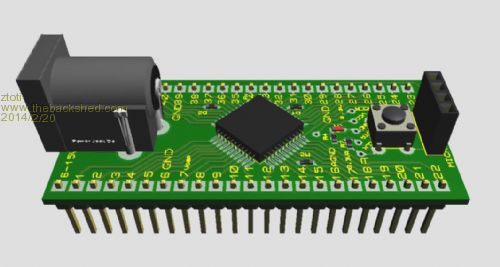
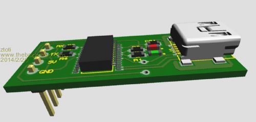
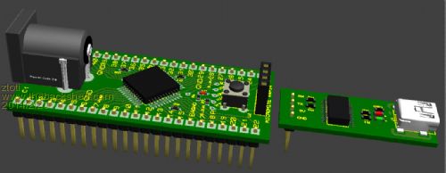
Hello, There is my idea for micromite. The microcontrolers I use for hardware design and I was so happy with micromite idea. Anyway, in my case USB/serial converter I use just for programming and debugging and when job is done I don't need it any more. That is a reason why I maked 2 PCBs: Micromite and USB board. Another thing, for many projects I need 12-15V DC for relay, motors...so this is perfect place for step down converter to provide 3.3V on output and input of 12V to drive some load. This Micromite version will works with 5-15V on DC jack or 5v from USB/serial converter as well. I'm happy to share my version with this great community. https://dl.dropboxusercontent.com/u/42611861/MICROMITE.pdf https://dl.dropboxusercontent.com/u/42611861/Micromite44PIN% 20-%20CADCAM.ZIP https://dl.dropboxusercontent.com/u/42611861/MICROMITE_USB%2 0-%20CADCAM.ZIP |
||||
| JohnL Senior Member Joined: 10/01/2014 Location: SeychellesPosts: 128 |
Ztoti, Very good idea to keep Micromite and usb adapter boards separate. Once Micromite is programmed and deployed, there is no need for usb adapter. Couple of suggestions: - try to make USB adapter pinouts same/compatible with the cheap ebay etc. adapters. 3.3v,5v,Txd,Rxd,Gnd. http://www.ebay.com.au/itm/USB-To-RS232-TTL-Auto-Converter-M odule-Converter-Adapter-For-Arduino-S9-E0Xc-/310807648933?pt =AU_CablesConnectors&hash=item485d945aa5&_uhb=1 - Provide an option for 2 pin PCB screw terminal connector for power connection. Basically provide pads/mounting holes next to power jack, so that either can be used. http://www.ebay.com/itm/50x2way-2Pin-Screw-Terminal-Block-Co nnector-5mm-Pitch-Panel-PCB-Mount-K2301-oo-/390733924938?pt= LH_DefaultDomain_0&hash=item5af98e8a4a - Also consider a Li-Ion battery connector with on board charger for portable applications, Micromite has provision to sleep/wake to conserve power. To help you take this further I would be interested in purchasing a large number of Micromite PCB's, subject to reasonable pricing. Regards JohnL |
||||
| WhiteWizzard Guru Joined: 05/04/2013 Location: United KingdomPosts: 2991 |
Hi Ztoti, Just to clarify, I have several versions of the 44pin MicroMite as I believe the end-user should be able to select the best-fit for their own requirements. I am working on the following options (regarding the 44pin version): 1> Just the PIC32 TQFP with cap & ICSP in a 44 pin DIP format as a plug in module to another PCB or BreadBoard (no PSU included) 2> As above but with 5v & 3v3 LDOs (similar to what you have designed) 3> Eval board designed to (beta) test the MicroMite's features all on one breadboard friendly module including USB-to-uart, ICSP, dedicated 3v3 500mA LDO and reset button. No need to include switches, LEDs etc as this is what you use the breadboard for - i.e. total flexibility to the user. If you keep the MicroMite & USB separate I will assure you some people will ask for them to be combined; and vice versa. For that reason I am offering these multiple combinations. It would be easy to add this that and the other, but then that is why it is breadboard friendly! I also have a LiPo board option with higher voltage/power outputs - design in final stage. I like your graphics very much - which app did you use? Regards, Phil |
||||
Lou Senior Member Joined: 01/02/2014 Location: United StatesPosts: 229 |
Ztoti, WhiteWizzard, guys, Your boards all look good, different functionality for different folks... I would try to keep the PICkit program header on all the boards though. I was talking to Zonker a couple days ago. Maybe we can come up with one or more good 44-pin board designs and ask CircuitGizmos or SparkFun or someone else with distribution capabilities if they want to produce and stock them, pre-built and/or or bare boards. Then we could all get them in any quantities. Any thoughts... Anyone with experience on how that would work out ?? I think the uMite has possibilities beyond all the Picaxe type products. Lou Microcontrollers - the other white meat |
||||
| ztoti Regular Member Joined: 27/10/2011 Location: CanadaPosts: 65 |
Hi all, I said this is my vision of Micromite, what I need to do my pcb for my project. If somebody like it, this is free to download. JohnL thanks for suggestion, I already start to make a new version with Li-ion connector and charger . About USB/serial adapter, I made it to be compatible with Parallax/Propeller and with Micromite but I'll make a new version. Zoran |
||||
| JohnL Senior Member Joined: 10/01/2014 Location: SeychellesPosts: 128 |
Another suggestion Zoran. You mentioned in your earlier post that you intend to drive relays, motors etc. Any thoughts of including ULN2803 octal driver on board, to drive OC loads up to 50v, 500ma? I would strongly suggest a DIL socket for ULN2803, for easy replacement. |
||||
| ztoti Regular Member Joined: 27/10/2011 Location: CanadaPosts: 65 |
Hello, I added to the PCB some improvements: Li-Ion charger, 5 pin connector for USB/serial, Li-Ion connector and I made 2 versions, with DC Jack and with terminal block. Tomorrow I will update a new version of USB/serial with 5 pins and the gerber files. Sorry JohnL, no room for ULN2803, this version has to be small DIP package. Cheers Zoran 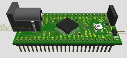
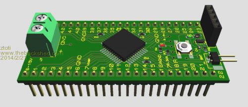
https://dl.dropboxusercontent.com/u/42611861/MICROMITE3D_1.p df https://dl.dropboxusercontent.com/u/42611861/MICROMITE3D_2.p df ps. If any problem with DropBox, please check file extension ".pdf" not ".p df" |
||||
| The Back Shed's forum code is written, and hosted, in Australia. | © JAQ Software 2026 |
