
|
|
Forum Index : Microcontroller and PC projects : Keyboard for Micromite Plus
| Author | Message | ||||
| Chris Roper Senior Member Joined: 19/05/2015 Location: South AfricaPosts: 280 |
Beware that the PIC16F1455 has very tight Timing requirements to stay in sync with the USB. I have seen reports that even responding to an interrupt can throw the USB off. If you are very proficient with C and have a fully optimised compiler you may get away with it if the scanning is not too time sensitive but I think you may be better off with a larger PIC18 device in this application. I must add that is just hearsay on my part, I am new to using USB on the 8 Bit PIC's, having only used it in the PIC32 so far, so I am not really qualified to give advise 
Cheers Chris p.s. Your 9x8 matrix is not able to generate the Ctr-Alt-Del sequence so the user could get stuck if the windows 10 virus ever infects the Miromite. MS did say that their intention is to have WIN 10 on EVERY device  http://caroper.blogspot.com/ |
||||
| MicroBlocks Guru Joined: 12/05/2012 Location: ThailandPosts: 2209 |
Chris, Yes i have read about that too. Hopefully the article i linked in my post solves that problem as it is a complete USB stack developed to make it more robust. I have a few chips on the way, then we will know for sure. :) Actually the Ctrl+Alt+Del is on one single row. So if that row is activated you can mask those 3 bits and check all the three keys in one go. :) If it is wired with 15 as the MSB and 23 as the LSB then an AND with 10110000 will check for that combination. [code] 15 | 16 | 17 | 18 | 20 | 21 | 22 | 23 | ----------|------|------|------|------|------|------|------| 01 02 04 14 24 | Ctrl | | Del | Alt | Fn | Shift| Cmd | Right| [/code] I purposely combined the keys on the single row so that i can add a 4 input (N)AND to generate a real reset signal by combining the row pin and the 3 (15,17,18) columns. Also other interesting control combination are possible with that row of keys that can be captured not only in software but can be decoded in hardware pretty easy. Microblocks. Build with logic. |
||||
| Chris Roper Senior Member Joined: 19/05/2015 Location: South AfricaPosts: 280 |
Damn, my joke backfired, you had already thought of WIN 10 
Thanks for that link, it looks very useful and well written. I have been banging my head against the wall trying to use the Microchip Code Library. From now on I am switching to this. Having the entire stack trimmed of fluff and interrupt driven makes a huge difference. I have no Idea why Microchip didn't do it that way in the first place. So I have lots of reading and testing to do this weekend as I work through those articles. Cheers Chris http://caroper.blogspot.com/ |
||||
Grogster Admin Group Joined: 31/12/2012 Location: New ZealandPosts: 9985 |
UPDATE: F9/9 - (11,16) F10/0 - (12,16) | - (10,18) ALL keys have now been tested and work with the LED, so I think it is safe to design from now, TZA. 
Here is the modified, updated and correct hand-written table: 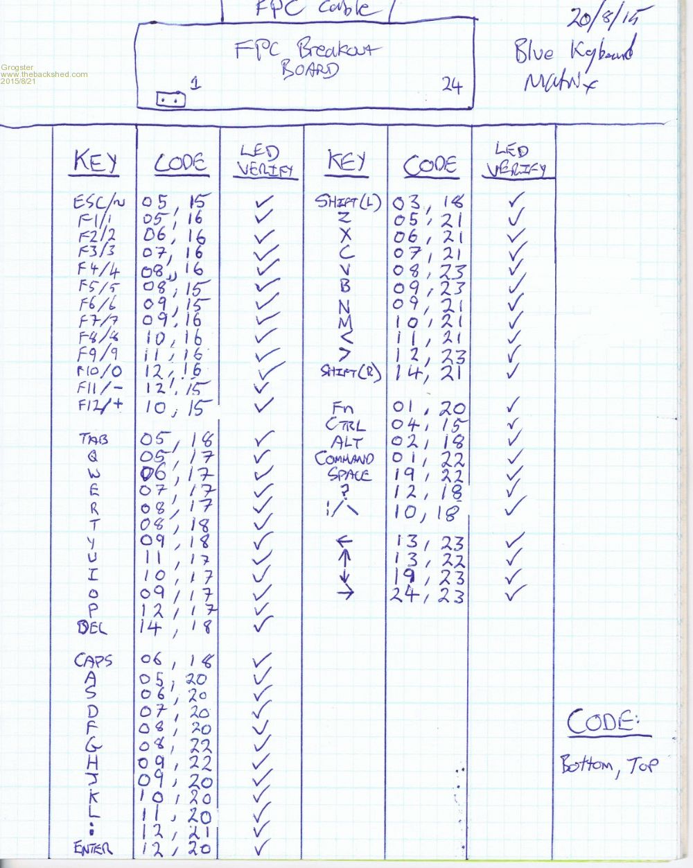
Smoke makes things work. When the smoke gets out, it stops! |
||||
| MicroBlocks Guru Joined: 12/05/2012 Location: ThailandPosts: 2209 |
G, Can you check what the delete key does. On the picture i can see a big arrow to the left that would suggest it is a backspace. Does that mean it will be a delete when combined with another key (Alt Option)? When combining rows i have a few options, depending on the functionality of this key i might have to change it. Unfortunately the Ctrl+Alt+Del is not possible anymore on one row. :( This is the updated matrix before combining rows. [code] 15 | 16 | 17 | 18 | 20 | 21 | 22 | 23 | ----------|------|------|------|------|------|------|------| 01 | | | | | Fn | | Cmd | | 02 | | | | Alt | | | | | 03 | | | |ShiftL| | | | | 04 | Ctrl | | | | | | | | 05 | Esc/~| F1/1 | Q | Tab | A | Z | | | 06 | | F2/2 | W | Caps | S | X | | | 07 | | F3/3 | E | | D | C | | | 08 | F5/5 | F4/4 | R | T | F | | G | V | 09 | F6/6 | F7/7 | O | Y | J | N | H | B | 10 | F12/+| F8/8 | I | |\/ | K | M | | | 11 | | F9/9 | U | | L | < | | | 12 | F11/-| F10/0| P | ? | Enter| : | | > | 13 | | | | | | | Up | Left | 14 | | | | Del | |ShiftR| | | 19 | | | | | | | Space| Down | 24 | | | | | | | | Right| [/code] And here is the updated (sofar) combined rows matrix. In my plan i have to use more pins from the 4040B as the smallest matrix is now 11x8. [code] 15 | 16 | 17 | 18 | 20 | 21 | 22 | 23 | ----------|------|------|------|------|------|------|------| 01 04 14 24 | Ctrl | | | Del | Fn |ShiftR| Cmd | Right| 02 13 | | | | Alt | | | Up | Left | 03 19 | | | |ShiftL| | | Space| Down | 05 | Esc/~| F1/1 | Q | Tab | A | Z | | | 06 | | F2/2 | W | Caps | S | X | | | 07 | | F3/3 | E | | D | C | | | 08 | F5/5 | F4/4 | R | T | F | | G | V | 09 | F6/6 | F7/7 | O | Y | J | N | H | B | 10 | F12/+| F8/8 | I | |\/ | K | M | | | 11 | | F9/9 | U | | L | < | | | 12 | F11/-| F10/0| P | ? | Enter| : | | > | [/code] Microblocks. Build with logic. |
||||
| Grogster Admin Group Joined: 31/12/2012 Location: New ZealandPosts: 9985 |
Hi - 'Delete' key with the left arrow would be a backspace, I would expect. I never connected either of my test KB's up, as I have no Bluetooth devices here for it to pair up with. It is in the correct place for backspace though, so that is how I am treating it - as backspace. Smoke makes things work. When the smoke gets out, it stops! |
||||
| robert.rozee Guru Joined: 31/12/2012 Location: New ZealandPosts: 2541 |
the 4040 is a ripple counter, as such each output will toggle at half the rate of the previous one. so for stepping over addressing 11 rows you'll need 2048 (2^11) clock pulses. a 4017 decade counter may be a better choice if you can reduce the matrix down to 10 rows. or you could bite the bullet and charlieplex the keyboard, in which case you may be able to use no separate decoding logic. cheers, rob :-) |
||||
| Grogster Admin Group Joined: 31/12/2012 Location: New ZealandPosts: 9985 |
In my design, which is not as fancy as TZA's,  , I am just going to use a 44-pin MM chip, and run a continuous matrix scanner, and output the keys on COM1. , I am just going to use a 44-pin MM chip, and run a continuous matrix scanner, and output the keys on COM1.
That works amazingly well for my 8 x 8 test matrix. I realize this one is a little bigger, but when the ONLY thing the code ever has to do, is round-and-around she goes.... That's all I need, but I think TZA is going for full USB HID beast. Smoke makes things work. When the smoke gets out, it stops! |
||||
| MicroBlocks Guru Joined: 12/05/2012 Location: ThailandPosts: 2209 |
@Rob, You are right. I had the 4017 datasheet in front of me and was looking for a few more outputs and found the 4040. Not at all a good choice as it is indeed a ripple counter.Thanks for the warning, that would have been an unpleasant situation. I have made a schematic of the keyboard matrix to help me better visualize it. Here is a schematic of the matrix: 2015-08-21_174017_Matrix.pdf Combining different rows i gota better result then my first try. I can get it down to 9 rows and 8 columns. This will allow the use of the 4017 again, which is great. I was a bit concerned because if there were more then 10 rows needed a totally different approach had to be taken. I know the charlieplexing but i not particular like the extra diodes and also the ghosting effect. And here the revised matrix with rows combined. The first row has most of the special keys like Ctrl, Del, Fn, Cmd. Having the Space (Fire), Up, Down, Left, Right and Esc in the next 3 rows allows for a more rapid scanning for games if only those keys are needed. Also other useful keys in 'game mode' are F1/F2/F3 and both shifts. [code] 15 | 16 | 17 | 18 | 20 | 21 | 22 | 23 | ----------|------|------|------|------|------|------|------| 01 04 14 | Ctrl | | | Del | Fn |ShiftR| Cmd | | 05 19 | Esc/~| F1/1 | Q | Tab | A | Z | Space| Down | 06 13 | | F2/2 | W | Caps | S | X | Up | Left | 03 07 24 | | F3/3 | E |ShiftL| D | C | | Right| 08 | F5/5 | F4/4 | R | T | F | | G | V | 09 | F6/6 | F7/7 | O | Y | J | N | H | B | 10 19 | F12/+| F8/8 | I | |\/ | K | M | | | 02 11 | | F9/9 | U | Alt | L | < | | | 12 | F11/-| F10/0| P | ? | Enter| : | | > | [/code] If someone can check this matrix for errors that would be much appreciated. It is so easy to make a mistake. My goal with using a PIC16455 (maybe a 16459 if i need more pins) is to be able to use 3 kinds of interfaces. First and foremost Serial so that the keyboard can be easily used with most MCU's. I have a few future projects in mind that needs to use the USB, this chip allows a HID so without a hardware change it can also be used for that. Third it can use I2C. This is low priority but the hardware will allow it. The PIC and the 4017 together will be about 2US$, so it will be cheaper then using a 44 pinner micromite. Software is a bit more difficult (especially the USB) but that is just a challenge. :) Microblocks. Build with logic. |
||||
| Grogster Admin Group Joined: 31/12/2012 Location: New ZealandPosts: 9985 |
Beautiful schematic of the matrix, TZA - work of art!  
Makes it so much easier to see how it is "Wired up", and the colours really help to keep the different rows/columns visually separate to stop confusion. Excellent. 
I will cross-reference your matrix with what I have here. I know you will have already done that yourself, but as you say - extra set of eyes, and it certainly IS easy to make a mistake with matrices of this size - look at the few errors you picked up on my initial probing!
I really like your approach - I will be watching this with MUCH interest, as if it can do serial, USB KB and maybe even I2C at some stage, it will be a VERY flexible KB unit indeed. Smoke makes things work. When the smoke gets out, it stops! |
||||
| MicroBlocks Guru Joined: 12/05/2012 Location: ThailandPosts: 2209 |
My little blue keyboard arrived yesterday. Did not get it to work yet on my windows computer with bluetooth. But that is not really a problem anyway. :) I had to laugh about the 'aluminium' part as described in the ebay text. It is really flimsy and the only structural strength comes from the plastic case. I think a plastic bottom or a more solid aluminum one will change it into a pretty useable keyboard. Adding some rubber strips will keep it more steady. My chips should arrive from the Microchip factory on the 28th, so just a few days more before can test some things. Probably next weekend. Microblocks. Build with logic. |
||||
| Grogster Admin Group Joined: 31/12/2012 Location: New ZealandPosts: 9985 |
Yeah, that backplate is pretty useless, really,  and I am getting 3mm aluminium plate cut using the old flappy one as a template. and I am getting 3mm aluminium plate cut using the old flappy one as a template. Smoke makes things work. When the smoke gets out, it stops! |
||||
| Grogster Admin Group Joined: 31/12/2012 Location: New ZealandPosts: 9985 |
TZA - I have cross-referenced your 8 x 9 matrix table, with what I have written out here, and it looks fine for every single key. In fact, I am going to steal your matrix configuration, if you don't mind, for use in my keyboard, as I can then do the scanning with a 28-pin SSOP chip. Smoke makes things work. When the smoke gets out, it stops! |
||||
| MicroBlocks Guru Joined: 12/05/2012 Location: ThailandPosts: 2209 |
Good to hear. I am busy with a schematic with the datasheet as a guide. No chips yet to test it. Microblocks. Build with logic. |
||||
| Grogster Admin Group Joined: 31/12/2012 Location: New ZealandPosts: 9985 |
TZA - While translating your 8 x 9 table into a PCB pattern - third row from bottom of your chart - Row 10 19 I think should just be Row 10? Row 19 is on line two of your chart, and is paired with Row 5... Smoke makes things work. When the smoke gets out, it stops! |
||||
| MicroBlocks Guru Joined: 12/05/2012 Location: ThailandPosts: 2209 |
Yes that is correct. It is just row 10. (I moved row 19 together with row 5 as it was a better match) This is the latest: [code] 15 | 16 | 17 | 18 | 20 | 21 | 22 | 23 | ----------|------|------|------|------|------|------|------| 01 04 14 | Ctrl | | | Del | Fn |ShiftR| Cmd | | 05 19 | Esc/~| F1/1 | Q | Tab | A | Z | Space| Down | 06 13 | | F2/2 | W | Caps | S | X | Up | Left | 03 07 24 | | F3/3 | E |ShiftL| D | C | | Right| 08 | F5/5 | F4/4 | R | T | F | | G | V | 09 | F6/6 | F7/7 | O | Y | J | N | H | B | 10 | F12/+| F8/8 | I | |\/ | K | M | | | 02 11 | | F9/9 | U | Alt | L | < | | | 12 | F11/-| F10/0| P | ? | Enter| : | | > | [/code] Microblocks. Build with logic. |
||||
| Grogster Admin Group Joined: 31/12/2012 Location: New ZealandPosts: 9985 |
Sweet. Thanks. Smoke makes things work. When the smoke gets out, it stops! |
||||
| MicroBlocks Guru Joined: 12/05/2012 Location: ThailandPosts: 2209 |
Here is what i have sofar. 2015-08-23_162908_X2Serial.pdf It allows 3.3v and 5v operation, can be powered by USB or Pickit. (Need to add powered by a Mite). A voltage divider is used so that with one pin a choice can be made which output mode the software is going to use. I start with only serial, but plan to add USB,I2C and maybe PS/2 or onewire. It can also function as a USB->Serial although that is not the main goal, but can be a nice added feature. Will see if i can get that to work. I am not sure if the voltage divider will work. RA4 will be put into input mode once the program starts. This should make it possible to read the analog value. After the output mode is determined the port will be switched to an output and will most of the time be a '1' to hold the 4017 in reset so that output Q1 is active. The software does not need to scan the whole matrix all the time. When Q1 is active all the other outputs (Q1-Q9) have a '0'. If a key is pressed then that '0' will appear on the inputs from the 1459. Only then a row scan will be started to determine on which row the key was pressed. The column(s) are already known. Just need to check for a '0' to '1' transition while scanning to determine the row(s). Do that a few times to debounce. Then go back to holding the 4017 in reset and check the input port again for another 0' to appear. This would be a very efficient way to scan the matrix as it is only done when a key is pressed. All the other time no scanning of the matrix will occur. At least that is the theory.
Microblocks. Build with logic. |
||||
| Grogster Admin Group Joined: 31/12/2012 Location: New ZealandPosts: 9985 |
Crafty idea using the 4017 counter.
Here is my version: TOP LAYER: 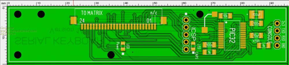
BOTTOM LAYER: 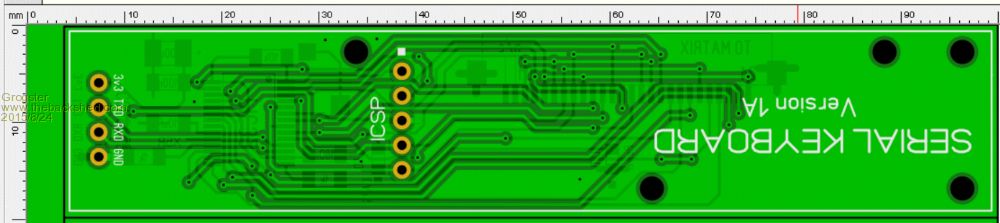
This board is designed to directly replace the existing Bluetooth board. Remove the securing screws and FPC cable, plop this board in it's place, and replace the FPC cable and screws. This board will then output plain serial for any key pressed at 19k2 baud. This one is not near as fancy as your one TZA, but it is a start. 3v3 supply from the host system, as my concept is designed to work in close proximity to the host, rather then on a big long cable, so one meter or so is all the cable I have allowed for. That, and I was too pressed for space to fit a 3v3 regulator!
I could get the reg in there, but there is no real-estate left for routing tracks! Smoke makes things work. When the smoke gets out, it stops! |
||||
| MicroBlocks Guru Joined: 12/05/2012 Location: ThailandPosts: 2209 |
Looks great and when it replaces the current pcb all the better. Instant keyboard! Would it be possible to salvage the powerbutton and connect button? The connect button would be a nice 'reset' Also maybe use the bluetooth location to blink a led when a key is send. This will give you a visual confirmation. Maybe the charge led as a aid for debugging. Visual clues are nice to have when testing. I am not perfectly happy with this little blue keyboard but can use it to test a matrix. I need something that can be used with lots of keypads/keyboards als long as they have a matrix of 9x8 or smaller. The pic 1459 is such a versatile chip that i choose it to base all my little modules on. Concentrating on a single pic will make it easier to understand all its details. Great for 'close to the metal' and when speed is needed. For everything else the Mites are the way to go. Microblocks. Build with logic. |
||||
| The Back Shed's forum code is written, and hosted, in Australia. | © JAQ Software 2026 |
