
|
|
Forum Index : Microcontroller and PC projects : Circuit diagram
| Author | Message | ||||
| MicroBlocks Guru Joined: 12/05/2012 Location: ThailandPosts: 2209 |
Hi Lew247, Got back home, still lots to do as not everything fitted in the truck! Have some large stuff like a lasercutter, lathe and mill to move and they did not quit fit. 
I am still wondering about the connections you used for the BME280 and TSL2561. Are you using a breakout board for those? If so which ones? Any other modules you are using? Pictures/datasheet/partnumbers of those available. I am getting close to the final board, so it is time for a good check. Microblocks. Build with logic. |
||||
lew247 Guru Joined: 23/12/2015 Location: United KingdomPosts: 1709 |
I just had a very long play with Diptrace and although I couldn't replicate your neatness (or use screw terminals as I don't have the Diptrace parts) I did manage to do a "kinda ok board" I have everything as headers the way I did it, but ideally to make connection easier/simpler everything should be screw terminals apart from the GPS module which I think will be neater plugged in direct via a header. If everything else is screw terminals it lets people place the sensors anywhere they like in whatever case they are going to use.  |
||||
| MicroBlocks Guru Joined: 12/05/2012 Location: ThailandPosts: 2209 |
Lewis, I see you got some more practice. 
It gets more easy after a while. I am already using it over two years so i am familiar with what can be done. One of the things i never use is depend on the auto router. I sometimes use it to see if placement is good, and for some simple designs it gets close. I then decide to use the auto routers result as a starting point or if it is really a mess i start from scratch and route everything by hand. Most of the time at the end every trace is hand placed/moved as auto routing is still not good enough. This is what i got so far: 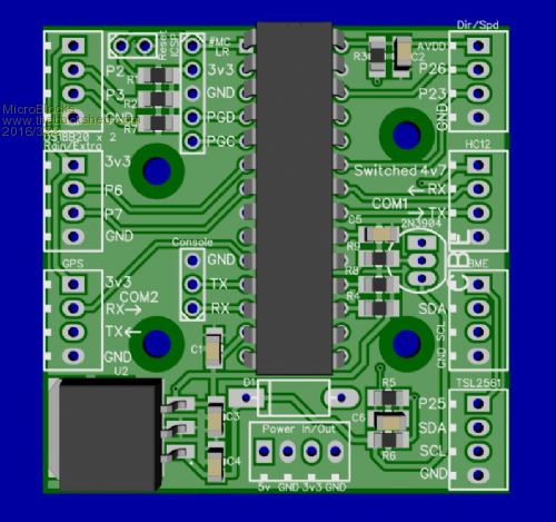
All the screw terminals are facing to the outside of the board making connections easy. They can also be headers as the pitch is the same 0.1". Not sure if the silkscreen for the screw terminals are right, the little dots might go on the inside, but that does only matter when the screw terminals have plastic notches that go into small holes in the pcb. I did not do that as the screw terminals i have in stock are flat on the bottom. Microblocks. Build with logic. |
||||
| lew247 Guru Joined: 23/12/2015 Location: United KingdomPosts: 1709 |
That is really impressive 
A couple of notes: I changed the diode (D1) to a STPS1L30U It's cheaper and smaller - it uses an smb footprint DS18B20 could pin 2 labelled Sun could Pin 3 labelled Shade and Rain pin 2 labelled Speed GPS needs power to go via transister/resistor/5V (or 4.7v) and pin 23 although I can use Pin 7 if you want as thats already on the board? See image below (this is to conserve power)  |
||||
| lew247 Guru Joined: 23/12/2015 Location: United KingdomPosts: 1709 |
IF there is no room for the transistor for the gps power then it's ok, leave it as it is, it only uses around 5mW so as long as the battery does get charged every day it should be fine. |
||||
| MicroBlocks Guru Joined: 12/05/2012 Location: ThailandPosts: 2209 |
Is the GPS 5v or 3.3v? Microblocks. Build with logic. |
||||
| HankR Senior Member Joined: 02/01/2015 Location: United StatesPosts: 209 |
MB, On the right side of the uC there are resistors R9, R8, R4, and another surface mount part I can't make out. These are a little close to the uC, especially if a socket is employed. Could there be just a smidge more room opened up, perhaps by simply sliding the uC a few hundredths of an inch to the left? HR |
||||
| lew247 Guru Joined: 23/12/2015 Location: United KingdomPosts: 1709 |
I'm using a gps module which can use anything from 5v to 2.6v I guess it would probably use a little less power using 3.3v instead of 5v Hank it's the capacitor for the Micromite that you can't identify |
||||
| HankR Senior Member Joined: 02/01/2015 Location: United StatesPosts: 209 |
I hope I can persuade Lew to make a slight change in what has become two power saving switches driving the GPS and the HC-12. We've been PMing about it. As now drawn, NPN transistors (Q1, Q2) are hooked up as "emitter followers" so it's not possible for them to deliver more voltage to these emitter driven loads than the base voltage, because these circuits have 100% voltage feedback where the output follows the input with an AC voltage gain of 1. That's where the name *emitter follower* comes from. For DC levels it's actually even worse, because the B-E junction voltage drop subtracts from the output, so it's going to be something like 3.3-.6 = 2.7 out (depending a little on load current and other factors). The solution is very easy: change to a PNP (2N3906 is the exact complementary part, but almost anything works) and switch emitter and collector leads. I've sent Lew the circuit. Even if the board stays as is, a twist of the two transistor leads will work. Hank |
||||
| lew247 Guru Joined: 23/12/2015 Location: United KingdomPosts: 1709 |
Hank's suggestion is a good one All it really needs is the silk screen for the board to show the the 2N3906 pinout instead of the previous one (pnp instead of npn) (pins reversed) 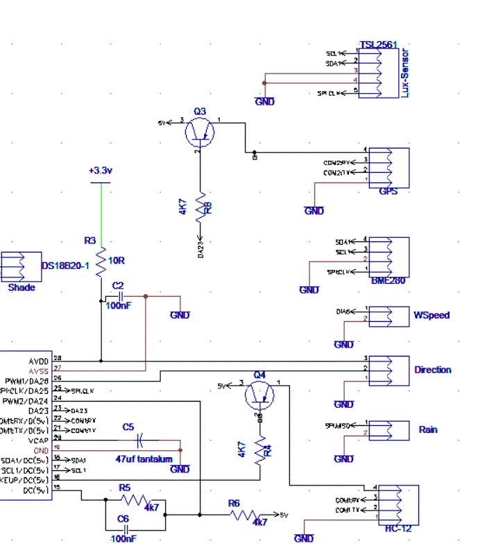
|
||||
bigmik Guru Joined: 20/06/2011 Location: AustraliaPosts: 2981 |
Hi Lew, You have the emitter and collector reversed. In your schematic... (If my transistor logic has not left me far behind) Regards, Mick Mick's uMite Stuff can be found >>> HERE (Kindly hosted by Dontronics) <<< |
||||
| lew247 Guru Joined: 23/12/2015 Location: United KingdomPosts: 1709 |
Sorry you're right corrected below (hopefully) I wish there was a way to delete posts that need deleting like the circuit above!!!!! 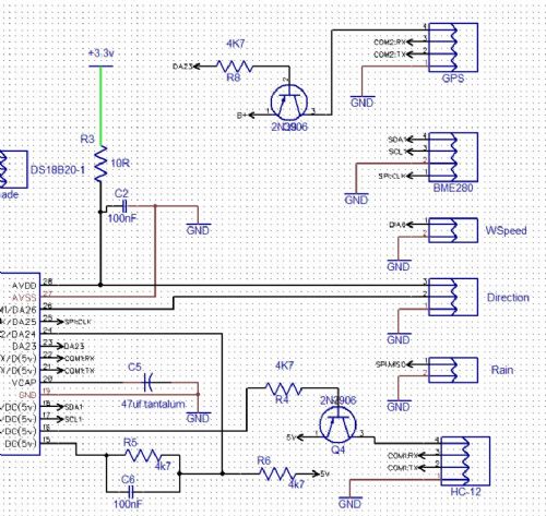
|
||||
| MicroBlocks Guru Joined: 12/05/2012 Location: ThailandPosts: 2209 |
When the output pin of the uMite is in a high-z state or configured as in input, what would then be the effect on this transistor? The base of the transistor is then basically floating. Or in other words is the transistor 'on' when the uMite starts up or 'off'? I normally use a pullup or pull down resistor to make sure the state during startup is known. Would that not be better? Microblocks. Build with logic. |
||||
| HankR Senior Member Joined: 02/01/2015 Location: United StatesPosts: 209 |
The transistors will not be conducting so the peripheral devices being controlled will not be running. Based on the above statement, you'll be able to answer that question definitively, but I'd guess the startup condition of the uMite is with I/O pins floating. That in turn means the peripherals will not be running (usually a good thing). No, I don't think so. It's an unnecessary part. If it makes you feel better you could do it. With a floating state, the startup situation is perfect with the circuit just as it is now. |
||||
| lew247 Guru Joined: 23/12/2015 Location: United KingdomPosts: 1709 |
Last and definitely last minor mod MicroBlocks I've been thinking about that one pin on your board that isn't used and decided a UV index sensor would be ideal it uses the same i2c pins as used in the other 2 sensors plus pin 7 that you already had routed in your board PDF of the circuit attached and also the diptrace circuit 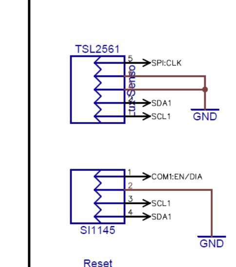
2016-03-23_203315_DipTrace_Schematic_-_Weather_16.pdf 2016-03-23_203355_Weather_16.zip |
||||
| lew247 Guru Joined: 23/12/2015 Location: United KingdomPosts: 1709 |
Got the board a nice 50mm X 50mm now
I really need to find 3D images for Diptrace of headers and most of the other components Anyone got a decent set of files for Diptrace they dont mind sharing? components, connectors, screw terminals and so on? 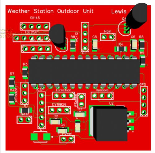
|
||||
| bigmik Guru Joined: 20/06/2011 Location: AustraliaPosts: 2981 |
Hi Lew, All, I have been looking at your transistor circuit again and I dont think it will work as you expect it to. The basic premise is to conduct across the emitter/base to turn the transistor ON.. This means applying a LOW to the BASE will conduct across the emitter/Collector... OK that works.. BUT The maximum voltage you can apply to the base driven as shown is 3v3 which would still mean that as this is more than 0.6v less than the emitter's 5V level that the transistor is still ON.. Personally I think a better solution would be to use some Opto-Isolators to do the job.. Open to feedback.. There are many cobwebs in my brain where I stored my transistor logic theory.. Kind Regards, Mick Mick's uMite Stuff can be found >>> HERE (Kindly hosted by Dontronics) <<< |
||||
| bigmik Guru Joined: 20/06/2011 Location: AustraliaPosts: 2981 |
GDay Lew, Looks OK, but some constructive criticism.... Firstly you would not be able to use screw terminal blocks the way you have them layed out, you are limited to male/female headers (not that that is a realy problem if that is what you want) Secondly I would increase the track thickness for all of the power rails, (5V, 3v3, GND) I generally use 0.01" for signal tracks and 0.025" for power tracks (or 0.20" if space is tight) Regards, Mick Mick's uMite Stuff can be found >>> HERE (Kindly hosted by Dontronics) <<< |
||||
| bigmik Guru Joined: 20/06/2011 Location: AustraliaPosts: 2981 |
GDay Lew, All, You mentioned you wanted some form of battery backup.. I think the simplest method is to use a XIOAMI powerbank like this one. XIOAMI 1040mAhr The genuine powerbank has a nice feature that clones and other cheapo units don't have in that it can charge itself and supply power to your product at the same time so you could insert one of these in line with your 5V power source and if the 5V source dies (power failure) the battery bank will take over automatically and when power is restored it will recharge itself whilst still supplying power to your board.. I use one of these on a board I made, with the assistance of Peter Carnegie with some smart coding, to create a terminal emulator for my work that emulates a terminal running on 2 x RS485 4 wire lines and it will keep the micro mite running for a few days before needing a recharge.. I think you could do away with switching GPS etc on and off and rely on the power bank to keep it running... If you might have power outages of longer than a couple of days you can probably monitor the 5V input to the power bank and go low-power until power is restored, that way you could probably stay up for months. This particular unit is 10400mAhr and will deliver 2A max so that should power, lets assume 200mA max draw (prob no where near that) will keep you going at full power for 50hrs. They have smaller 5200mA and larger 20800mA units. Just a caveat, there are a lot of fake units out there so I suggest you buy from a reputable company, see the video clips on the link above. Regards, Mick Mick's uMite Stuff can be found >>> HERE (Kindly hosted by Dontronics) <<< |
||||
| HankR Senior Member Joined: 02/01/2015 Location: United StatesPosts: 209 |
Mick, You are correct with the present state of the circuit. So good catch there. As originally conceived by Lew, the feed to the peripherals was 3.3 volts, just like the uC. In that instance, no problem in the standard configuration shown in the schematic (except going back to 3.3 volts on the emitter) which is used all the time. uC output pin low = switched loads supplied with 3.3 volts (across load terminals) and current. uC output pin high = switched loads have no current. and, just to be thorough, uC pin floating = switched loads have no current. To stay with 5 volts going to the switched loads, a circuit mod using only one more transistor and resistor will do it nicely. Details in a later post. Of course, with an optoisolator you can do almost anything, even controlling an AC load. Hank |
||||
| The Back Shed's forum code is written, and hosted, in Australia. | © JAQ Software 2026 |
