
|
|
Forum Index : Microcontroller and PC projects : MM+, Explore 64 and Explore 100
| Author | Message | ||||
Grogster Admin Group Joined: 31/12/2012 Location: New ZealandPosts: 10005 |
Hey Rob. 
Unfortunately, through-hole multi-pin connectors are one of the hardest to remove from boards with plated-through-holes, which is most boards, really. 
The piezo IS ACTIVE. If you put DC on these piezos from Altronics, they squeal continuously. I have not tried a passive piezo so I have no idea if it would work or not. Re. RTC markings for four-pin end of module - can remove the markings, but as they do reflect what the markings say they are, I thought it was a good idea to label them - even though they are not technically used. I guess you are thinking that some may well think that these pads give them access to the 5v PSU and the I2C bus, which they don't. That is indeed a very valid point. I will have to start a notepad list of things for possible changes to a 1C version of the board! 
You should also note there are 2.5mm holes on the RTC footprint so that you can use 2mm bolts, spacers and nuts(or threaded spacers) to anchor the RTC to the board, but in all seriousness, this isn't really necessary - the module is self-supporting on the pin-strips just fine. 2:33AM - Grogster sleep now........  Smoke makes things work. When the smoke gets out, it stops! |
||||
| Phil23 Guru Joined: 27/03/2016 Location: AustraliaPosts: 1667 |
One other method I've used in the past for stripping boards is the Hot Air gun. Have successfully managed to heat a group of pins so the devices just dropped out. I did notice on this board that the pins had good clearance. What I don't know is how the board survived; Visually it looked fine, no signs of overheating. (Unlike the odd occasion I've dropped things off with a mini blow torch). 
Still would rather destroy the connector than damage the board. Is the heat gun method considered safe? Or just don't go there? (When I've used that method I was only interested in component recovery, not the board). Thanks Phil. |
||||
| robert.rozee Guru Joined: 31/12/2012 Location: New ZealandPosts: 2542 |
personally, i've not had good success with heatgun and through-hold components in regards to not damaging the board. i would still favour destroying the connector, perhaps hacksawing it into pairs of pins. bear in mind that the connector is worth a dollar or two at most, while the board loaded with the rest of the components is worth considerably more. cheers, rob :-) |
||||
| Grogster Admin Group Joined: 31/12/2012 Location: New ZealandPosts: 10005 |
It's a problem in some respects. Through-hole plating on modern boards means that once you solder something like those headers in place(anything with more the a few pins, really), then removing them becomes more problematic, as the solder "Glues" the pins to the through-hole plating, making the part MUCH more difficult to remove then a single-layer board, which are dead easy to remove the same part from. I still think Chip-Quik is the best method, as it also allows you to use a relatively low iron temperature during the whole process, meaning you are less likely to lift tracks or pads or cause any other PCB damage. I have heard of the hot-air gun method, but have never used it myself. I am probably not the only one to not want to recommend that approach, but if you wanted to try it, that is up to you.  Smoke makes things work. When the smoke gets out, it stops! |
||||
| Phil23 Guru Joined: 27/03/2016 Location: AustraliaPosts: 1667 |
Hi Rob, Just grabbed the heat gun & the original failed heat pump controller board & removed a couple of 10 pin DIL connectors with it. Bit Ho-hum, I got them off, but not happy enough to try in on a good board. Mind you, they were tight fitting square pins in the round holes, the ones on these connectors are a pretty free fit in the holes. Did take about 30 seconds of heat though. Think I will probably try nipping the plastic away with some cutters & then take the pins out individually. Is this the correct socket? They don't state it's height. Also wonder if anyone knows RS's Part# for either of the Piezos, may as well grab them as well. Only have Jaycar here & theirs is too high. These are 4 that I've found. http://au.rs-online.com/web/p/piezo-buzzer-components/6173069/ http://au.rs-online.com/web/p/piezo-buzzer-components/0457055/ http://au.rs-online.com/web/p/piezo-buzzer-components/0237956/ http://au.rs-online.com/web/p/piezo-buzzer-components/6221382/ None state the lead spacing. Also what's the small vs large piezo thoughts? Is the bigger on preferable? Thanks Phil. |
||||
| Phil23 Guru Joined: 27/03/2016 Location: AustraliaPosts: 1667 |
Holly Smokes, Chip-Quik is not cheap stuff...... Not sure exactly which product you mean. |
||||
mikeb Senior Member Joined: 10/04/2016 Location: AustraliaPosts: 180 |
@Phill Heat is a PCB's worst enemy. If you wish to save the PCB you must reduce the component to individual pins. Therefore your only option is - 1) Destroy the connector housing, carefully, with 'snipe nosed' side cutters, leaving the individual pins exposed. This gives you something to hold onto, with tweezers, without sinking too much heat from the joint. 2) Grasp the pin, with tweezers, and apply heat to the joint. Try to rock the pin back and forth and, as soon as it is COMPLETELY FREE, pull the pin out of the board. DO NOT apply a 'pulling' force until it is completely free. You risk lifting the pad on your side of the board, or worse, pulling the plated through tube out of the hole. 3) Allow the PCB to cool before moving on to the next pin. Once all pins have been removed you can clear the holes of solder. Once again, do not apply excessive heat. Personally, I use a desoldering station, but the 'heat and tap' method has merits as does the 'solder wick' approach. The key is not to apply too much heat, or force, in one go but take your time, and allow the PCB to cool between operations. I have successfully removed very large 'pin count' components from PCB's, in the past, using the above method. Remember - DO NOT APPLY EXCESSIVE HEAT and TAKE YOUR TIME. @Everyone If your 'piezo' device does not have any polarity markings then it is a 'passive' device and therefore needs an alternating 'drive' signal which the designated pin does not provide. There are 10 kinds of people in the world. Those that understand binary and those that don't. |
||||
TassyJim Guru Joined: 07/08/2011 Location: AustraliaPosts: 6553 |
A long time ago... A friend had a new Macintosh computer. It was one of the first ones and had sod all memory. He purchased a memory upgrade kit and asked me to help fit it. The original ram was soldered onto the main board instead of using sockets. My friend looked startled when I went and got the angle grinder out of the shed ready to start removing the chips. He was relieved when I attacked my side cutters and not his pride and joy. I trimmed the cutters down enough to snip each pin individually and then removed them one at a time with a small iron and long-nose pliers. The pins attached to the power and ground planes were the worst. We were both relieved when the new chips (with sockets) went in and the computer still worked. I still prefer the 'one pin at a time' approach and blowing the solder from the holes has only resulted in a few burnt lips. Jim VK7JH MMedit |
||||
| mikeb Senior Member Joined: 10/04/2016 Location: AustraliaPosts: 180 |
@All Just as an 'aside' here is the 'dump' I got at the 'command prompt' when I had shorted 'console port' pins - 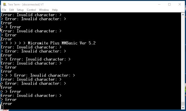
At my stage of life I like to think about problems before 'posting'. I like to think it wards off Dementia 
Note that this was a continuously scrolling dump. There are 10 kinds of people in the world. Those that understand binary and those that don't. |
||||
| Zonker Guru Joined: 18/08/2012 Location: United StatesPosts: 772 |
One picture worth a thousand words..!! 
|
||||
| Grogster Admin Group Joined: 31/12/2012 Location: New ZealandPosts: 10005 |
@ Phil23 - Yes, Chip-Quik is very expensive, but it just saves so much mucking around, that..... It is a common complaint - the price of the stuff. But IMHO, I don't care about the price of something like this(within reason, naturally!) if it works. Chip-Quick does work, and it makes removing stuff like this so easy, you hardly have to think about it. No, I don't work for them.  
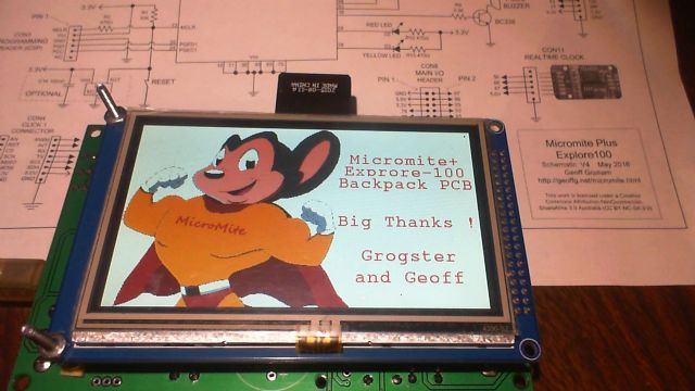
mikeb is spot-on with his comments about making sure you fully heat the solder when removing pins using the cutting method. If you try to pull the pin out when the solder is not fully melted through to both sides of the board, you can indeed lift pads, tracks or vias - or all of those at once. @ Zonker - Glad to see it arrived to you OK. Nice image. 4.3 inch screen? Smoke makes things work. When the smoke gets out, it stops! |
||||
| Phil23 Guru Joined: 27/03/2016 Location: AustraliaPosts: 1667 |
Ok, Thanks for all the feedback everyone. I went down the road of cutting the plastic away bit by it & removing a few pins as I went. Fortunately due to their good clearance in the holes the pins almost dropped out of their own accord. No visible damage to the board; gave it a light clean with fluxed up solderwick & Alcohol & fitted the header from my 2nd kit & it's up & running fine. Got a prompt, Graphics & Touch all Ok. Cheers. Probably won't need to much Alcohol myself now. |
||||
| robert.rozee Guru Joined: 31/12/2012 Location: New ZealandPosts: 2542 |
am glad to hear the removal was a success. you can get replacement headers here: http://www.ebay.com/itm/381374497534 (5pcs 2.54mm 2x20 Pin Double Row Female Pin Header, us$1 including shipping) it is the same price for 1, 2, or 5. you can pay by paypal or credit card. credit card payments are processed through paypal too, and are extremely secure - the seller never sees your credit card details. cheers, rob :-) |
||||
| Grogster Admin Group Joined: 31/12/2012 Location: New ZealandPosts: 10005 |
Well done you. 
Yes, I like to make the holes for headers a little bigger then they really need to be. Mainly, this is to allow for alignment issues later. If the holes are a perfect fit for the thing you are installing, and the other mating side is NOT, then you can have a mis-match, and the damn things won't align right. SLIGHLY oversize holes allow you to move the header just a fraction to line it up with the pins. In any event, it was a good thing, cos you got it out OK. Nice work.  Smoke makes things work. When the smoke gets out, it stops! |
||||
| Phil23 Guru Joined: 27/03/2016 Location: AustraliaPosts: 1667 |
Thanks Rob, Reason I was going to pay for some from RS is the delivery time. Most overseas ebay stuff is about 2 weeks to here. As long as it's the right height. Also can anyone confirm if any of the RS piezo's I mentioned would be correct. Cheers. |
||||
| Grogster Admin Group Joined: 31/12/2012 Location: New ZealandPosts: 10005 |
All I can tell you at this point, is that the piezo was designed to use one of the two Altronics part numbers, which are printed on the bottom silkscreen. Goto Altronics, and put in those S part numbers. Smoke makes things work. When the smoke gets out, it stops! |
||||
| Phil23 Guru Joined: 27/03/2016 Location: AustraliaPosts: 1667 |
Yes I've looked at them on Altronics, the only reason I looked at RS was a quick source of the 40 way connector; free freight... If I can't be sure RS has one that suits, I'll just cop Alt's extra freight. But still haven't heard comment of the small vs the large, or if it's even relevant. |
||||
| Grogster Admin Group Joined: 31/12/2012 Location: New ZealandPosts: 10005 |
As far as I know, the size is not relevant. When Geoff built his very first alpha prototype using a TQFP breakout board, he was using the big peizo, so this was what we designed into the board. Later on, Geoff instructed me to change the footprint, so that you could use either piezo to give people more options. Basically, any 9-12v continuous-tone piezo sounder should work fine, provided it fits. However, to be 100% certain, then you need to use one of the specified ones - or try one of your own ones. You could just tack-solder it on for the purposes of testing..... Smoke makes things work. When the smoke gets out, it stops! |
||||
| WhiteWizzard Guru Joined: 05/04/2013 Location: United KingdomPosts: 2991 |
@Grogster Is there a simple line or two of code that you can post to test the 'touch beep' feature. I can PWM the buzzer - but want to get a 'click' on touch. Something I have never had to do before so any help appreciated! This will allow me to confirm my piezo's are ok
WW |
||||
| Grogster Admin Group Joined: 31/12/2012 Location: New ZealandPosts: 10005 |
Are you wanting to just check a piezo on ANY pin to see if it will work as the touch click piezo? If so, I have found that a simple PULSE pin,5 works well. You might need to increase that to 10mS or more, depending on the piezo. Most piezo's that run a continuous 1kHz tone(or whatever frequency), will still respond with a 'Click!' noise with a very short positive pulse like that, and I think that is exactly what Geoff does in the code, from what I remember him telling me at one point..... If you want to actually test the touch-click, and are using a piezo you know will work, then you set the click option as part of the touch command - see page 17 of the MM+ manual. Basically, OPTION TOUCH 1, 40, 39.......(Option Touch T_CS, T_IRQ, Click Pin) Smoke makes things work. When the smoke gets out, it stops! |
||||
| The Back Shed's forum code is written, and hosted, in Australia. | © JAQ Software 2026 |
