
|
|
Forum Index : Microcontroller and PC projects : Why doesn’t this work?
| Author | Message | ||||
| Warpspeed Guru Joined: 09/08/2007 Location: AustraliaPosts: 4406 |
I have just had a fairly similar dismal experience with using thirty rather unreliable relay contacts to monitor the voltage of thirty lithium cells. It seemed like a good idea at the time.... Cheers, �Tony. |
||||
Quazee137 Guru Joined: 07/08/2016 Location: United StatesPosts: 603 |
Opps swap the resistors and kill the led. LOL 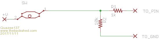 |
||||
Grogster Admin Group Joined: 31/12/2012 Location: New ZealandPosts: 9975 |
@ warpspeed - Indeed.  I have nothing against the mercury switches, but historically in this application, they got broken so I was 'Unwilling' to use them again, despite how well they actually work. I have nothing against the mercury switches, but historically in this application, they got broken so I was 'Unwilling' to use them again, despite how well they actually work.@ quazee137 - change 'TO_GND' to Vcc, and '+V' to Ground, and you have what I have on the hacked one now. IE: Pin is pulled up via resistors, and ball-switch is supposed to pull the pin down like any other switch in the world does with the 10k/1k arrangement. It does not. Some ball-switches DO, others do not, so they are not consistant, and they must indeed have some internal resistance or oxide layer or some such as has been discussed in this thread. The best laid plans of mice and engineers......  Smoke makes things work. When the smoke gets out, it stops! |
||||
Azure Guru Joined: 09/11/2017 Location: AustraliaPosts: 446 |
Grogster, just to satisfy my wandering mind, how far are these tilt switches located from the MM chip and if off board how are they wired up? New to the forums, hope to be able to contribute to the great work you are all doing. |
||||
| Grogster Admin Group Joined: 31/12/2012 Location: New ZealandPosts: 9975 |
Hello and welcome.  The ballswitch is about 15mm from the I/O pin on the MM chip. Very close. Smoke makes things work. When the smoke gets out, it stops! |
||||
redrok Senior Member Joined: 15/09/2014 Location: United StatesPosts: 209 |
Grogster;Do you have an actual specification for that ballswitch? Just curious. I've been experimenting with some type "102" mercury tilt switches. Their pretty cheap at 7.9 us cent each. Their rated for 1/2A at 20VAC. I find they have some quirks though: 1. These do bounce quite a bit even when carefully tilting them. The bounce rate is about 10/second. Maybe that is not a problem. As I recall you wanted to watch them with an interrupt. Will multiple interrupts be a problem? Maybe not? 2. Orientation of the switch seems to be important! My "102"s have one electrode that has a bend on the far end. This is important for switches that generally lay flat. The bend prevents the blob of mercury from getting trapped in the end of the glass tube. The blob rolls back and forth between the hook and contact. If the switch is oriented upside down, with the hook aimed "DOWN", some of my switches don't reliably make contact. I think it's because there is not quite enough mercury in the tube when laying flat so it doesn't quite touch the hook contact. However, with the hook aimed "UP" the blob rides along the hook and always makes good contact. Horizontal orientation also works fine. ------------------- 3. The resistance of this switch is very low, maybe a few milliOhms./ \ \ | | | In-Correct Up-Side-Down Orientation ----------\__/ | __ ----------/ \ | | | | Correct Right-Side-Up Orientation \ / / ------------------- I was doing some experiments with filtering the bounces. The simplest version is to put a 10uF cap across the switch with a 100K pullup resister. The 10uF discharges to 0V in under 1uS. Ya, that is really fast. I'm estimating the max discharge current is upwards of 10A. You couldn't do this with a dry contact but the mercury contact is unaffected. The RC constant is about 1 second. This should be enough time to cover several bounces. I also tried this with a 30uF and 100uF electrolytic. These also worked nicely and stretched out the bounce prevention time. redrok |
||||
| Quazee137 Guru Joined: 07/08/2016 Location: United StatesPosts: 603 |
This looks to be more of a mass problem or lack of. I made 3 different ball tilt switch mock ups the smallest ball fails a lot gold, tin and copper contacts does not matter. The next size ball works 70/30 there abouts. The largest ball works every time but at 3/8" is has the mass. I am waiting on a neighbor to drop off two sizes copper plated lead (buck shot) to try out in place of the two smaller ones. I did find a few sources for the type you posted but they are modules. All of them seem to use heat shrink no real seal. Maybe your working units have a good seal. (could try adding a 2nd ball) The cheap newer types clamming they are mercury replacements has two balls to help with the mass needed and are sealed at adafruit.com they look to be gold plated too. Quazee137 |
||||
| Grogster Admin Group Joined: 31/12/2012 Location: New ZealandPosts: 9975 |
@ redrok and others - These are the ball-switches I am using, but I also tried these green ones. The black/red ones are bi-directional, which is why I chose them. The green ones are just a ball in a metal tube with an isolated contact at one end, so only form a circuit when tipped in the right direction. Two of these green ones would make one black/red one, but the green switches probably have exactly the same problem. @ Quazee137 - Can you provide a link to the adafruit ones please? These are the mercury switches I am about to play with. I will need two of these to detect a tilt either left or right, but mercury switches have historically always 'Just worked' due to their simplicity. Smoke makes things work. When the smoke gets out, it stops! |
||||
| Quazee137 Guru Joined: 07/08/2016 Location: United StatesPosts: 603 |
Here is the link and a few more. adafruit 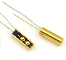 The sunfounder show the same type but the pictures show one like adafruit . sunfounder 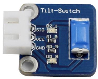 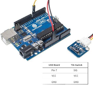 And wiltronics ball-tilt-switch-module with code. wiltronics While shopping Digi-Key found RB-441-45 different from how your doing but its one switch. on till tilted in any direction Datasheet and 10 for $14.45. I don't know if there is some one that carries ckswitches there. And maybe a way to still use what you have. 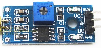 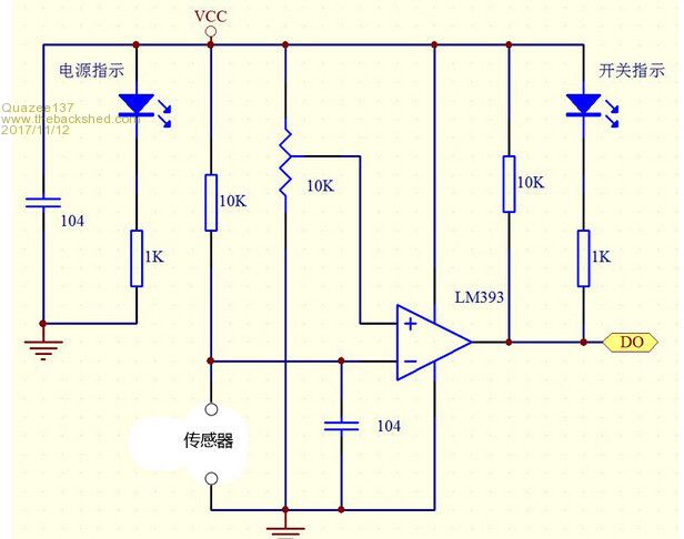 but use the little 5 pin opamp 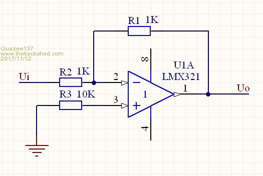 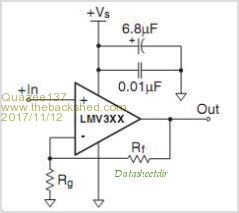 it takes little power to run. Quazee137 |
||||
| The Back Shed's forum code is written, and hosted, in Australia. | © JAQ Software 2026 |
