Home
JAQForum Ver 24.01
Log In or Join  
Active Topics
Local Time 03:29 22 Sep 2026 Privacy Policy
Jump to

Notice. New forum software under development. It's going to miss a few functions and look a bit ugly for a while, but I'm working on it full time now as the old forum was too unstable. Couple days, all good. If you notice any issues, please contact me.

Forum Index : Electronics : Inverter building using Wiseguys Power board and the Nano drive board

     Page 41 of 41    
Author Message
KeepIS

Guru

Joined: 13/10/2014
Location: Australia
Posts: 2267
Posted: 07:07am 21 Sep 2026
Copy link to clipboard 
Print this post

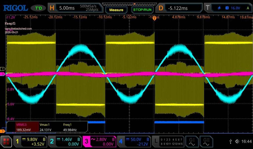
Something I did for fun. No VFB 20V DC supply.

A: Test Inverter, Power board with 34,000uF.
B: DC voltage DOES NOT CHANGE, monitored with A DSO.  
C: No AC Feedback connected, besides it's below VFB activation in any case.
D: Inverter powered by regulated 20Vdc supply with a max current of 21 Amperes.

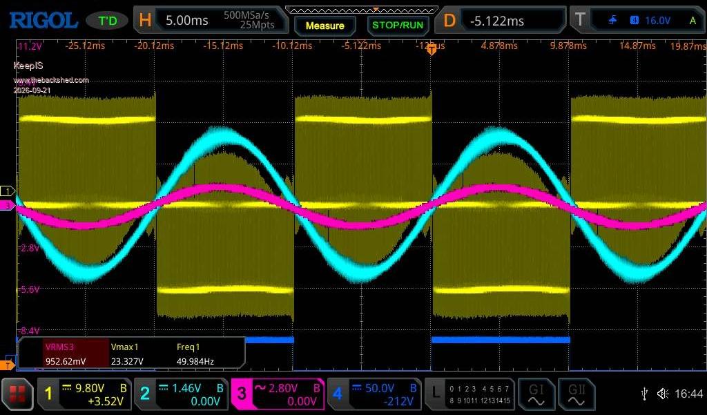
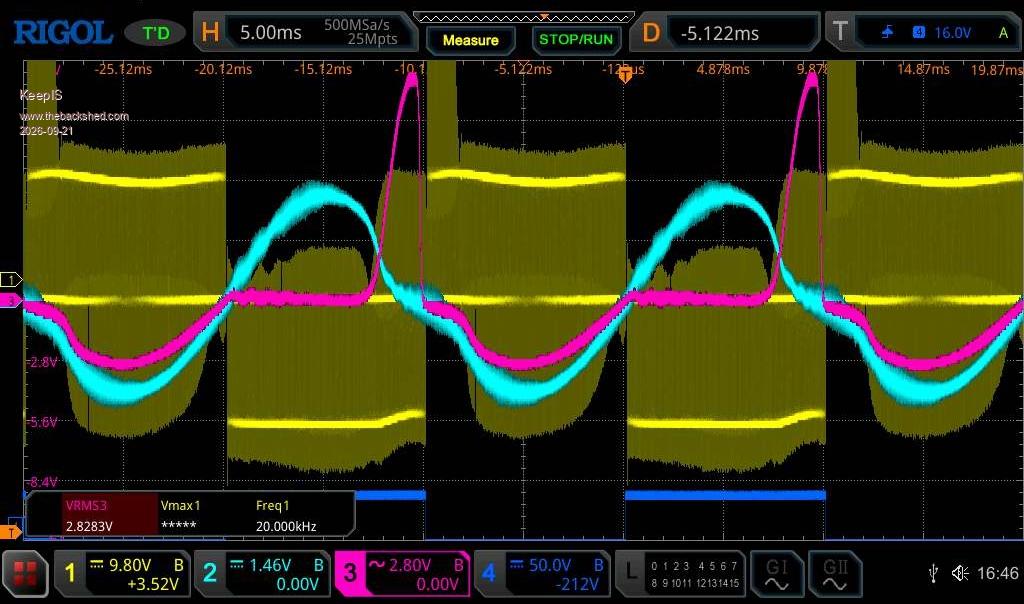
Pink: Primary Current.
Blue: LT AC output.  

Capture 1: Idle.


Capture 2: 180w Restive Load.

A: 11.5A Primary current via Clamp meter.  
B: 12A  vPrimary current via TLS76L1.


Capture 3: Heat Gun.

A: 34A Primary current via AC clamp meter.
B: 35A Primary current via TLS76L1.
C: DC current switches between 11A and 20A every few seconds.
D: Buzz in Toroid does not change with that swing.  


.
NANO:Inverter V 8.4ksLinux AvrDude GUI script V4.1
 
wiseguy

Guru

Joined: 21/06/2018
Location: Australia
Posts: 1316
Posted: 07:49am 21 Sep 2026
Copy link to clipboard 
Print this post

Great image shots and good idea to remove feedback as Nicks also recently did. The yellow drive waveform appears to be phase reversed compared to the output - it just made it a bit harder to interpret at first.

Maybe my analysis below is wrong or questionable, I am not trying to speak with authority, its just a theoretical comment and I invite comments for or against.

The peak voltage for the positive unloaded 180 degrees is ~ 2 divisions, The peak for the loaded negative 1/2 wave is ~ 1.5 divisions. The result of the asymmetrical waveform results in the positive unloaded current but with saturation peaks.

This is why I described our toroids as "puny" compared to the mains. With a distorted waveform such as this applying feedback might make it even worse as it tries to drive harder for the lower average output? My suggestion of 180 degree measurements and applying them to the second 180 degree waveform - not the next immediate period should try to prevent or at least partially mitigate the issue of the low negative toroid drive voltage. I am unsure but suspect that changing the phasing of the feedback might only make a small difference on the idle hum.

I am not telling you or anyone to write the code but I can see an issue that we can either accept or have a further play with the code to see if we can get a better result. I am happy to offer up my inverter as a sacrificial unit for testing if it makes any difference.
Edited 2026-09-21 18:07 by wiseguy
If at first you dont succeed, I suggest you avoid sky diving....
Cheers Mike
 
     Page 41 of 41    
Print this page


To reply to this topic, you need to log in.

The Back Shed's forum code is written, and hosted, in Australia.
© JAQ Software 2026