
|
|
Forum Index : Microcontroller and PC projects : Armmite - STM32H7: Developments
| Author | Message | ||||
| TrevorH Senior Member Joined: 06/04/2018 Location: United KingdomPosts: 145 |
Peter, I have tested both other drivers on 5.04.23 and the 8bit one the text became almost readable. The earlier drivers I had no success at all, after loading the .elf file OK, back in MMedit I couldn't load basic file to nucleo although cmd line calls worked eg. cls, "error talking to Micromite" if I recall. I think you are correct about the speed, I had this problem with my CPLD driver when I tried to speed things up. I had to introduce "nop"s into the WR toggle to get the display to accept the data. |
||||
| matherp Guru Joined: 11/12/2012 Location: United KingdomPosts: 11474 |
Just to be sure.... You are powering the display separately from the Nucleo? The display takes more on the 3V3 line than the Nucleo can supply. LD5 the overcurrent LED will flash to indicate this. I use an external 3V3 supply to the display with the grounds connected. |
||||
| TrevorH Senior Member Joined: 06/04/2018 Location: United KingdomPosts: 145 |
I am powering display separately and LD5 is off. Just tried something else, if I do text with FC red the text is OK with some errors. I will try and do some tests with my 7inch SSD1963 display tonight, it is possible not all displays work as fast as others?? maybe. Can't do any more this afternoon, grand-kids sports day! PS. do you have NO wait states in the WR toggle. Trevor. |
||||
| TrevorH Senior Member Joined: 06/04/2018 Location: United KingdomPosts: 145 |
Still here, I have done a few more tests and the corruption is definitly when FC is WHITE, also when using other colours for FC if I define the BC, errors disappear. Trevor. |
||||
| matherp Guru Joined: 11/12/2012 Location: United KingdomPosts: 11474 |
Attached is version 5.04.24 2018-07-12_013125_Armmite.zip This fixes IR which is now tested and working. The DISTANCE command is also checked and working. It also introduces an additional parameter for the SSD1963 which controls the speed of writing. Usage should be obvious from the listing below. GUI TEST LCDPANEL is also used to give comparative speeds The three drivers are: SSD1963_5 ' eight bit driver Full speed 117 circles per second Throttled speed 64 circles per second SSD1963_5_16 'sixteen bit driver Full speed 298 circles per second Throttled speed 175 circles per second SSD1963_5_buff ' sixteen bit driver with a full in-memory image. Full speed 394 circles per second Throttled speed 206 circles per second The latter uses a big chunk of user memory but can significantly reduce screen artifacts when updating and will be considerably faster for things like drawing circles and triangles 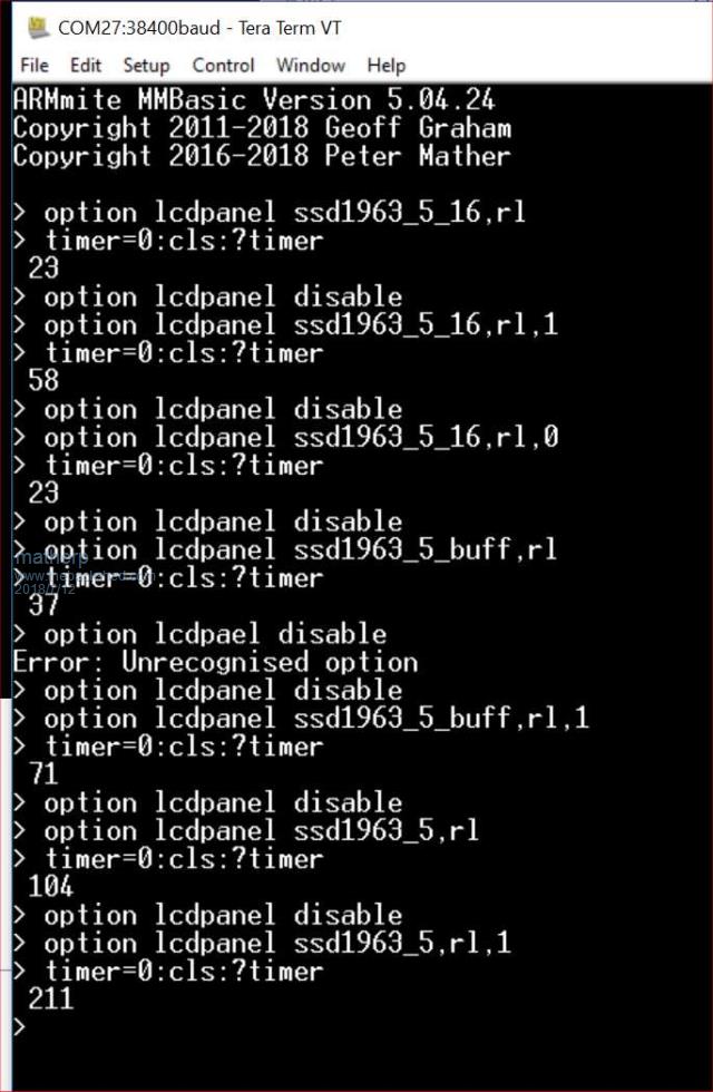 |
||||
| cdeagle Senior Member Joined: 22/06/2014 Location: United StatesPosts: 269 |
Is there a way to turn off the check for the SD card? Thanks for all the great work everybody |
||||
| matherp Guru Joined: 11/12/2012 Location: United KingdomPosts: 11474 |
Don't understand the question or the intent |
||||
TassyJim Guru Joined: 07/08/2011 Location: AustraliaPosts: 6536 |
The resistors on my module are all 10k from signal line to 3.3V They all test OK. There are no series resistors. I expect I have a sh*tty contact somewhere. It's a long wait for a replacement. Jim VK7JH MMedit |
||||
| TrevorH Senior Member Joined: 06/04/2018 Location: United KingdomPosts: 145 |
Hi Peter, I have tried using the new speed related drivers with no luck. I have moved on to the 7 inch just to see if it might have been my 5" display causing the problem, again no change.  Here is a screen shot of some "text" tests, quality from my Samsung Tab not the best. 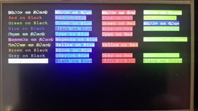 'Testing different text colours on different colour backgrounds for the Armmite 'Using 7 inch ssd1963 TFT with OPTION LCDPANEL SSD1963_7_16,RL cls text 20,20,"White on Black",,2,,rgb(white),rgb(black):text 220,20,"White on Blue",,2,,rgb(white),rgb(blue) text 420,20,"White on Red",,2,,rgb(white),rgb(red):text 600,20,"White on Green",,2,,rgb(white),rgb(green) Text 20,45,"Red on Black",,2,,Rgb(red):text 220,45,"Red on Blue",,2,,rgb(red),rgb(blue) text 420,45,"Blue on Red",,2,,rgb(blue),rgb(red):text 600,45,"Red on Green",,2,,rgb(red),rgb(green) text 20,70,"Green on Black",,2,,rgb(green):text 220,70,"Green on Blue",,2,,rgb(green),rgb(blue) text 420,70,"Green on Red",,2,,rgb(green),rgb(red):text 600,70,"White on Blue",,2,,rgb(white),rgb(blue) text 20,95,"Blue on Black",,2,,rgb(blue):text 220,95,"Black on Blue",,2,,rgb(black),rgb(blue) text 420,95,"Blue on Red",,2,,rgb(blue),rgb(red):text 600,95,"Blue on Green",,2,,rgb(blue),rgb(green) text 20,120,"Cyan on Black",,2,,rgb(cyan),rgb(black):text 220,120,"Cyan on Blue",,2,,rgb(cyan),rgb(blue) text 420,120,"Cyan on Red",,2,,rgb(cyan),rgb(red) text 20,145,"Magenta on Black",,2,,rgb(magenta):text 220,145,"Magenta on Blue",,2,,rgb(magenta),rgb(blue) text 600,145,"Magenta on Green",,2,,rgb(magenta),rgb(green) text 20,170,"Yellow on Black",,2,,rgb(yellow):text 220,170,"Yellow on Blue",,2,,rgb(yellow),rgb(blue) text 420,170,"Yellow on Red",,2,,rgb(yellow),rgb(red) text 20,195,"Brown on Black",,2,,rgb(brown):text 220,195,"Brown on Blue",,2,,rgb(brown),rgb(blue) text 20,220,"Grey on Black",,2,,rgb(gray):text 220,220,"Grey on Blue",,2,,rgb(gray),rgb(blue) text 420,220,"Grey on Red",,2,,rgb(gray),rgb(red):text 600,220,"Grey on Green",,2,,rgb(gray),rgb(green) text 20,245,"Black on White",,2,,rgb(black),rgb(white):text 420,245,"Black on Red",,2,,rgb(black),rgb(red) text 220,245,"Black on Blue",,2,,rgb(black),rgb(blue):text 600,245,"Black on Green",,2,,rgb(black),rgb(green) The lower left below "Grey on Black" is "Black on White" and resembles top left "White on Black", not clear on photo. It's weird certain colours react differently. Trevor. |
||||
| cdeagle Senior Member Joined: 22/06/2014 Location: United StatesPosts: 269 |
When I try to download a MMBASIC program using MMEdit I get the following error message, XMODEM RECEIVE "TEMP.BAS" Error: SD card not found I do not currently have an SD card attached to the H743ZI. Hence my question about bypassing the check for an SD card. I have ordered an SD breakout, so it's really not a big deal. |
||||
| matherp Guru Joined: 11/12/2012 Location: United KingdomPosts: 11474 |
This is the syntax for downloading a file to the SD card Just use "XMODEM RECEIVE" to load into memory |
||||
| cdeagle Senior Member Joined: 22/06/2014 Location: United StatesPosts: 269 |
The XMODEM RECEIVE "TEMP.BAS" message is displayed after the load and run command is issued from within MMEdit. I'm not sure how to do what you suggest. Thanks Peter |
||||
| TrevorH Senior Member Joined: 06/04/2018 Location: United KingdomPosts: 145 |
Just a thought, am I the only one getting this problem with the Armmite & TFT? Anyone?? Trevor. |
||||
| matherp Guru Joined: 11/12/2012 Location: United KingdomPosts: 11474 |
Sounds like you have the syntax drop down in MMEdit incorrectly set. Choose "Micromite_X_V5.3" |
||||
| cdeagle Senior Member Joined: 22/06/2014 Location: United StatesPosts: 269 |
Thanks Peter. Syntax change worked. I had an older version of MMEdit. I will be testing some of my astronomy programs on the H743ZI. |
||||
| matherp Guru Joined: 11/12/2012 Location: United KingdomPosts: 11474 |
Excellent  I always use your solar eclipse code to test my various versions for accuracy. |
||||
| matherp Guru Joined: 11/12/2012 Location: United KingdomPosts: 11474 |
No there is an issue but I'm certain it is electrical rather than code: My original results with your test program: option lcdpanel ssd1963_5_16,rl,1 - perfect option lcdpanel ssd1963_5_16,rl,0 - Corruption of white-on-black and black-on-white otherwise OK option lcdpanel ssd1963_5_BUFF,rl,1 - perfect option lcdpanel ssd1963_5_BUFF,rl,0 - Corruption of black-on-white otherwise OK option lcdpanel ssd1963_5,rl,1 - random small sections of background missing (typically 2 chars per run) option lcdpanel ssd1963_5,rl,0 - random small sections of background missing (typically 3 chars per run) BUT I then put a 47pF capacitor between WR and GND on the display and the results for all the 16-bit driver versions were then perfect but the 8 bit results were worse Basically I think we need a daughter board to get a good connection to the display. The signals from the STM32 seem to "ring" more than those of the PIC |
||||
| TrevorH Senior Member Joined: 06/04/2018 Location: United KingdomPosts: 145 |
Hi Peter, Thanks for your reply, you have sort of put my mind to rest (thought I was going nuts). I am close to completing my own daughter board (after drilling what seems to be an endless number of holes). I must admit I don't like using patch wires for these displays but needs must, I think as clock speeds rise problems also rise. Will try your remedy and play a little with values, hope the daughter board works first time will keep you posted. ps. did you do the driver mods to the 7 inch drivers?, if not will go back to the 5 inch. pps. any update on your daughter board thoughts? Thanks again for your continued interest in my problem. Trevor. |
||||
| TrevorH Senior Member Joined: 06/04/2018 Location: United KingdomPosts: 145 |
Hi Peter, The 47pf fix did not help on my setup or even 150pf. I have at last got my TFT daughter board working after corrections which eliminates the long wires. My tests are as follows:- SSD1963_5_16,rl,0 - corruption of white/black,white/blue,magenta/black,yellow/black and black/white SSD1963_5_16,rl,1 - PERFECT SSD1963_5_buff,rl,0 - corruption of black/white only others OK SSD1963_5_buff,rl,1 - PERFECT SSD1963_5,rl - mostly corrupt some OK SSD1963_5,rl,1 - PERFECT Are you introducing WR wait states or are you slowing down the processor in the ...rl,1 drivers? Trevor. |
||||
| matherp Guru Joined: 11/12/2012 Location: United KingdomPosts: 11474 |
Here is a first cut (as yet unrouted) for a Nucleo-144 daughter board. It supports: Battery for RTC SSD1963 ILI9341 ESP8266 module connected to COM3 OV7670 camera I/F I2C pullups Micro-SD card Jack socket for DACs Micro-USB socket for 5V input power (use Pi3 PSU or similar) Comments and ideas appreciated 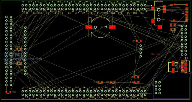 Much more complicated than that You can access a GPIO port by writing to the complete port (ODR=output data register) GPIOE.ODR = 16-bit number or you can write to a pair of registers that either set one or more bits GPIOE.BSRRH = 16-bit mask (any bit in the mask sets the IO bit) or clear one or more bits GPIOE.BSRRL = 16-bit mask (any bit in the mask clears the IO bit) To set an individual bit using the first method you first have to read the register change the bit and then write the complete register back (read-modify-write). C does this for you with instructions like: GPIOE.ODR ^= GPIO_PIN_4; GPIOE.ODR ^= GPIO_PIN_4; //Toggle pin GPIOE4 off then on The second method is a single atomic instruction and is much faster GPIOE.BSRRL = GPIO_PIN_4;GPIOE.BSRRH = GPIO_PIN_4; //Toggle pin GPIOE4 off then on The fast version of the drivers use the BSRRL and BSRRH registers to toggle WR. The slow versions use the ODR I have a slight suspicion that mixing the two can cause problems in that the BSRRL, BSRRH, and ODR registers may be out of synch for short periods in particular circumstances but I'm unable to prove it. |
||||
| The Back Shed's forum code is written, and hosted, in Australia. | © JAQ Software 2026 |
