
|
|
Forum Index : Microcontroller and PC projects : Armmite - STM32H7: Nucleo 144 backpack
| Author | Message | ||||
| lizby Guru Joined: 17/05/2016 Location: United StatesPosts: 3811 |
Thanks--all good now with GUI INTERRUPT. PicoMite, Armmite F4, SensorKits, MMBasic Hardware, Games, etc. on FOTS |
||||
| Lappa Newbie Joined: 24/03/2019 Location: AustraliaPosts: 6 |
Is anyone selling the backpacks in Australia? Cheers |
||||
| seco61 Senior Member Joined: 15/06/2011 Location: AustraliaPosts: 205 |
Hi. I recently ordered 10 PCBs and the components to populate them. I can probably sell 5 of them... I have 5 of the nucleo H7 boards so will keep 5 backpacks. I can also vouch for JLCPCB - extremely quick turnaround, very cheap and they did not charge me the postage for my first order! I assembled the first one last night - that is a hell of a lot of soldering!! There must be something like 500 solder joints to make (including the connector on the nucleo board - I did install all of the available connectors on the backpack board). It worked after I fixed the one solder joint that did not take correctly (the +5V pin on the micro USB connector - they are a bugger to solder!). Uploaded the latest 5.05.06 firmware with ST-Link with no issues. I attached a 5" SSD1963 display and a console connection via a USB-serial converter and now I have to port some of my programs to it. But it is all working well (well done Peter). I also put an extra long 3 pin connector on the console port so that I could connect to it from both sides of the PCB - very handy when the display is attached. Regards Gerard (vk3cg/vk3grs) |
||||
| matherp Guru Joined: 11/12/2012 Location: United KingdomPosts: 11636 |
I tin the PCB and connector, then lots of flux and use the heatgun until the connector settles into the solder, let cool, check connections, then solder the legs. Works for me. I use 2 tricks for this. One is to use right angle headers for the console, but the best is to stand the display off using these. I cut the pins so they sit flush into the existing 40 pin socket on the backpack. Then you can get connectors to all the backpack pins with no issue 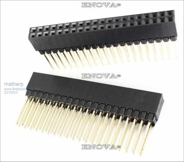 |
||||
| seco61 Senior Member Joined: 15/06/2011 Location: AustraliaPosts: 205 |
Hi Peter. I followed your suggestion and used the extended headers. I did not cut the legs and used 23mm stand-offs (an 8mm and 15mm together using a 15mm and 6mm screw). This gave plenty of room for all the other connections - though I still connect the console cable to the back... Regards Gerard Regards Gerard (vk3cg/vk3grs) |
||||
| The Back Shed's forum code is written, and hosted, in Australia. | © JAQ Software 2026 |
