
|
|
Forum Index : Microcontroller and PC projects : Armmite H7: Full release & documentation
| Author | Message | ||||
| KeepIS Guru Joined: 13/10/2014 Location: AustraliaPosts: 2177 |
Thanks but I already have that, I specificity wanted the two edge connectors in high detail, I took a photo and cropped the two edges, I wanted to add the processor pin number to the labelled edge connectors, all done and now I'm ready to get everything fitted up and experiment with a lot more ease. Thanks. NANO:Inverter V 8.2ks - Linux AvrDude GUI script V4.1 |
||||
| CaptainBoing Guru Joined: 07/09/2016 Location: United KingdomPosts: 2171 |
hmmm... the plop thickens. I set it all going last night and turned everything off and went to bed, this morning it is still blinking the red led. Only difference this time is no terminal session connected to the USB (unlikely to be a problem and all the other stuff turned off. So now I am suspecting power. That might also explain the total lock up with reset doing nothing... maybe... if I stare long enough at it. going to leave a terminal running but with minimal other stuff on, then turn on things one at a time... I suspect an LED light connected to a hub - which doesn't explain any power issues on a direct USB connection to my PC, but maybe both are on the limit. This bad boy can ask for a lot of juice (600mA+) Let's see what we find h |
||||
| CaptainBoing Guru Joined: 07/09/2016 Location: United KingdomPosts: 2171 |
this is the way I would go long term, I use a standard console connector with the USB thingie at the PC end standardized on a 3.5mm stereo jack for everything on the other. Means I can admin the devices with my phone too. Does the console output get "cloned" to PD8/9 by the firmware or are they taken to the ST-Link board on the nucleo? cheers |
||||
| matherp Guru Joined: 11/12/2012 Location: United KingdomPosts: 11515 |
They are the console connections - you can remove SB5 and SB6 if you wish which disconnects them completely from ST-LINK but a USB/UART seems to work fine with the USB unplugged |
||||
| CaptainBoing Guru Joined: 07/09/2016 Location: United KingdomPosts: 2171 |
Thanks, I looked through the nucleo doc for this info but I must be blind or something. cheers |
||||
| KeepIS Guru Joined: 13/10/2014 Location: AustraliaPosts: 2177 |
Apology if I'm cross referencing incorrectly, in the Manual Should RS be Pin-57 (PG1) and not PG11? SSD1963, 16-bit ILI9341 Connections Touch and SDcard connections as above DB0 Pin-141 (PE0) DB8 Pin-59 (PE8) WR Pin-125 (PG10) DB1 Pin-142 (PE1) DB9 Pin-60 (PE9) RS Pin-57 (PG11) DB2 Pin-1 (PE2) DB10 Pin-63 (PE10) RESET Pin-127 (PG12) DB3 Pin-2 (PE3) DB11 Pin-64 (PE11) RD Pin-128 (PG13) * NANO:Inverter V 8.2ks - Linux AvrDude GUI script V4.1 |
||||
| CaptainBoing Guru Joined: 07/09/2016 Location: United KingdomPosts: 2171 |
checked again, section 6.9... dammit  |
||||
| matherp Guru Joined: 11/12/2012 Location: United KingdomPosts: 11515 |
Yes: I'll fix it in the manual - thanks I use the circuit diagrams for this sort of thing - easier to find the info needed |
||||
| CaptainBoing Guru Joined: 07/09/2016 Location: United KingdomPosts: 2171 |
Morning Peter. Got another odd one for you. Isn't a problem but the corrupt character might signal something darker... Try running this tiddly bit of code: dim integer n,dir n=0, dir=0 Obviously the error is the comma on the last line but whence comes: 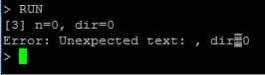 EDIT: just tried this on a MkII 44-pin jobby and it does the same - this looks like a long lived wrinkle in the root MMBasic code so @Geoff also |
||||
| Paul_L Guru Joined: 03/03/2016 Location: United StatesPosts: 769 |
I don't think you can use the comma as a statement delimiter, you have to use a colon. Try this: dim n%, dir% n=0:dir=0 Of course, the assignment is redundant. The dim command will probably automatically assign zero to integer variables. Paul in NY |
||||
| CaptainBoing Guru Joined: 07/09/2016 Location: United KingdomPosts: 2171 |
@Paul_L you are correct, of course, but that is not the point I am illustrating. The error was correctly picked up but the message contained a corrupt character (should have been an "=") h |
||||
| matherp Guru Joined: 11/12/2012 Location: United KingdomPosts: 11515 |
Definitely one for Geoff (to ignore?). I suspect this is because the "=" is tokenised and the error message is printing the token. If I'm correct this may be too difficult to fix to be worth the effort. |
||||
| CaptainBoing Guru Joined: 07/09/2016 Location: United KingdomPosts: 2171 |
yes, Small matter, so long as you are both aware. |
||||
| KeepIS Guru Joined: 13/10/2014 Location: AustraliaPosts: 2177 |
Two questions about SD card readers. Q1: All the pictures I've looked at for the SSD1963 5" and 7" (including Geoffs pictures) have small surface mount pads for an IC next to the SD card slot, but no IC is mounted there, I assume that the Card Slot works like this with the Armmite_H7? Q2: I know the interface SW was changed along the way and my next question is, will the small Arduino SD card boards work with the Armmite_H7? If not, is there a specific card reader I need. I know this may have been mentioned before but I can't find it among the many posts. Mike. NANO:Inverter V 8.2ks - Linux AvrDude GUI script V4.1 |
||||
TassyJim Guru Joined: 07/08/2011 Location: AustraliaPosts: 6538 |
The missing IC on the displays is not needed for the SDcard reader. There are some displays that have the touch panel and IC missing and I wouldn't want to end up with one of them. The SDcard uses SPI so any arduino module or similar will be OK. I have some with nothing except pullup resistors and others with a voltage regulator and even an IC. (The IC might be a level-shifter, I haven't looked) Some have the pinouts for 4 bit interface while others only have the SPI pins available. All seem to work OK. My preference is for the full size cards and an adapter for the microSD. It suits fumbling fingers better. The only problem I have is with a 4.3inch display but I am sure that it is the display PCB that is causing grief. It has issues on my MMX as well. Jim VK7JH MMedit |
||||
| KeepIS Guru Joined: 13/10/2014 Location: AustraliaPosts: 2177 |
Thanks Jim, that confirms everything. I have the correct displays, both 5" and 7" and have used all on the MM+ with touch, just never tried the SD holder on the LCD's before. Mike. NANO:Inverter V 8.2ks - Linux AvrDude GUI script V4.1 |
||||
| KeepIS Guru Joined: 13/10/2014 Location: AustraliaPosts: 2177 |
Just tried hooking up the console, external power, PD8- 77, PD9 - 78 and GND connected (RX,TX,GND), using a CP210x, I have a few, tried another, no go. Problem, If I press the reset button I get the CPYW info from the armmite received into the terminal window, so RX is fine, however it does not respond to anything sent from the terminal program? Checked leads, swapped, same, USB CN1 on H7 has nothing plugged in. Thoughts. Mike. NANO:Inverter V 8.2ks - Linux AvrDude GUI script V4.1 |
||||
| KeepIS Guru Joined: 13/10/2014 Location: AustraliaPosts: 2177 |
Fixed - I removed SB6 and everything runs, looks like some boards or USB-TTL boards don't like the link to CN1. NANO:Inverter V 8.2ks - Linux AvrDude GUI script V4.1 |
||||
| KeepIS Guru Joined: 13/10/2014 Location: AustraliaPosts: 2177 |
Just tried an SD card - used PG2 for the CS line and all others as per the latest manual. Set option sdcard 87 Type files and I get SD card not present. Option list shows: OPTION SDCARD 87, why the comma, does it want a card detect pin, there is none on the reader. SD reader is an Arduino compatible running from either 5v or 3.3, I'm running from 3.3v. SD card is a 4gb used in the MM-100. Where have I screwed up? NANO:Inverter V 8.2ks - Linux AvrDude GUI script V4.1 |
||||
| CaptainBoing Guru Joined: 07/09/2016 Location: United KingdomPosts: 2171 |
Check section 6.12 of the nucleo user guide here and the circuit diagram figure 16 at top middle. The console output comes from the processor and SB5 & 6 take it to the ST-Link daughter board. These two links sever that connection. With TX (out from the processor, it would work as the line is split between the morpho connector and the ST-Link virtual com port (USB) controller. But the same it true of the input, so your input to the RX line of the processor would be fighting with the same line from the ST-Link. hth h |
||||
| The Back Shed's forum code is written, and hosted, in Australia. | © JAQ Software 2026 |
