
|
|
Forum Index : Microcontroller and PC projects : LCD + Pico combo
| Author | Message | ||||
| Mixtel90 Guru Joined: 05/10/2019 Location: United KingdomPosts: 8989 |
@Tom The board as shown, wih a 68R (or whatever) resistor for R4, will work with any of the displays. The display will be dimmed on the older boards depending on the value and full brightness on the newer ones. It won't be software controllable though. If you want to dim the old displays your 2N3906 should be fine. Maximum backlight current is only 80mA and that is rated for 200mA. Look for a little chip on the back of the display with tracks to the Touch pins. Some versions of the display don't have it fitted. @Volhout Thanks for the info. Unfortunately I don't have a GPS of any sort so I'll just live with it. Eventually I'll get another module (or two - I can find a use for two now) in the hope that I got a rogue one. At least they are dead easy to swap out. :) Mrs Mixtel: "What can you use it for?" Hmmmmmm.... EDIT: The 12mm speaker on the Backpack is an *active* buzzer. They are very similar in appearance and, if you only want a click when a control is pressed, they both produce a brief click. However, GUI BEEP <tone_length> only works with an active buzzer. Usually the active devices are supplied with a sticker covering the hole whereas passive speakers aren't. The doc will be updated but not yet. Edited 2021-08-14 04:28 by Mixtel90 Mick Zilog Inside! nascom.info for Nascom & Gemini Preliminary MMBasic docs & my PCB designs |
||||
| Zonker Guru Joined: 18/08/2012 Location: United StatesPosts: 772 |
Good afternoon gents... I have tried the ILI9341 controller 320x240 display & the ILI9488 controller 480x320 display and both seem to have the same problem trying to get the screen touch calibrated... I thought I saw something about others also having this issue and was wondering if I somehow missed something... I have some other SPI based displays with one being an IPS type coming on the slow boat... For now these 2 are all I have to play with... Any feedback would be awesome... I didn't have much time to spend on this at first, but more time is opening up...  Much Thanks... Edited 2021-08-17 08:08 by Zonker |
||||
| lizby Guru Joined: 17/05/2016 Location: United StatesPosts: 3837 |
The reported solution, which also worked for me with the ILI9488 after many attempts, is to hold the first touch for a long time--some seconds. If I recall correctly, with my perfboard picomite, I also held the 2nd through 4th presses for a longer than usual time. This also worked on the PCB I had made by JLCPCB. That did not work for me with an ILI9341 on Mick's PCB. After some experimenting, after a long press worked for the first target, short presses only worked for the 2nd through 4th. But I don't think there is any guaranteed sequence. It probably took me 15 or more attempts to get it to work on Mick's board. I persisted because I knew it had taken many attempts to get it right before. I have no idea why there might be a difference from one board to another. PicoMite, Armmite F4, SensorKits, MMBasic Hardware, Games, etc. on FOTS |
||||
| phil99 Guru Joined: 11/02/2018 Location: AustraliaPosts: 3330 |
I recall someone else saying only momentary taps worked for them, but that was several firmware revisions ago. |
||||
| Zonker Guru Joined: 18/08/2012 Location: United StatesPosts: 772 |
Well, I tried the short touch approach and that got the second target to come up... After second touch it says "touch cal failure"... If I press & hold the target, then it seems to go crazy just repeating "touch not calibrated" Power down/reset only out of that one... Tried about 15 times... Will take some scope shots later... Thanks for the help gents..!!  |
||||
| Mixtel90 Guru Joined: 05/10/2019 Location: United KingdomPosts: 8989 |
Try just using GUI CALIBRATE 0, 362, 287, 897, 678 The chances are that it will be about right. :) It took me ages to calibrate mine. *lots* of attempts, but it managed it eventually with no errors. I got the above result back. Edited 2021-08-17 18:03 by Mixtel90 Mick Zilog Inside! nascom.info for Nascom & Gemini Preliminary MMBasic docs & my PCB designs |
||||
| Zonker Guru Joined: 18/08/2012 Location: United StatesPosts: 772 |
Interesting... I had no idea you could type in the calibration results by hand... So, I typed them in and then tried to do the GUI Test Touch command but didn't get anything to show on the screen... Went back to trying to do the calibration by touching the targets... This time I can now hold the pointer on the targets and the firmware doesn't go crazy like before, but after the second target touch release, It still says "Touch hardware failure"... So, I think I will try testing these displays with another Micromite MM+ board and see if it works there... Time will tell... One step at a time... So, after you got yours to calibrate, then the touch test went ok I would assume... Thanks for all the feedback gents..!! |
||||
| matherp Guru Joined: 11/12/2012 Location: United KingdomPosts: 11683 |
This is what happens if the firmware is seeing the touch interrupt properly but isn't reading the position correctly. Check the SPI connections. Also if you are using a ILI9488 display you must disconnect the SPI MISO from the display as the chip has a fault and doesn't tri-state that pin. |
||||
| Mixtel90 Guru Joined: 05/10/2019 Location: United KingdomPosts: 8989 |
Yep, it tested fine after that. I found that the more I repeated the calibration the better the results seemed to be - failing at a later stage of the process. This may be my imagination, of course. It seemed to be that getting the first touch quite short then doing the others with a light touch in pretty rapid succession seemed to help. I might try setting up a Micromite and having a play at calibrating on that. I don't *remember* it being as difficult, but I may well be wrong. I wonder if slowing the clock right down might help? Mick Zilog Inside! nascom.info for Nascom & Gemini Preliminary MMBasic docs & my PCB designs |
||||
| Zonker Guru Joined: 18/08/2012 Location: United StatesPosts: 772 |
Wow.. Ok... that was it... Taking out the display "SDO (MISO) pin did the trick... I now get thru the GUI Calibrate clean with no errors.. GUI Calibrate on option list command shows 0,123,184,1254,862 Doing the touch test works fine now with the drawn lines showing up directly under the touch point... Excellent... Thanks Peter..!! |
||||
| Mixtel90 Guru Joined: 05/10/2019 Location: United KingdomPosts: 8989 |
Latest (and probably final) version of the Backpack version 1.07 manual: PicoMite Backpack 0828.zip Mick Zilog Inside! nascom.info for Nascom & Gemini Preliminary MMBasic docs & my PCB designs |
||||
| Mixtel90 Guru Joined: 05/10/2019 Location: United KingdomPosts: 8989 |
I spoke too soon. :) Some updates & additions (along with a couple of pretty pictures!) added to the Backpack version 1.07 manual. PicoMite Backpack 0926.zip . . Mick Zilog Inside! nascom.info for Nascom & Gemini Preliminary MMBasic docs & my PCB designs |
||||
| thwill Guru Joined: 16/09/2019 Location: United KingdomPosts: 4380 |
Hi Mick, I'm looking at mounting a buzzer (9042 integrated passive piezo) to one of your backpacks, which currently looks like this: 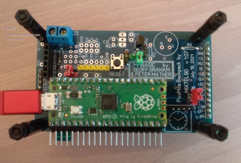 From your manual I think I'm supposed to put it over the top-right circle that can alternatively have a transistor on it, which holes should it be soldered into, do I need any botch wires or does the PCB have the connections ? The only other component I need is R3, correct ? This is supposed to be 560R which I don't have, would a 470R or 680R suffice or do I need to looking at bodging two resistors together in parallel or series to get something closer ? I also have a couple of no-name, no-id larger 12mm buzzers (one active and one passive) which I was wondering abut trying out. Can I safely try these and they will either work or not, or is there a danger of drawing too much current and releasing magic smoke ? Thanks, Tom MMBasic for Linux, Game*Mite, CMM2 Welcome Tape, Creaky old text adventures |
||||
| Mixtel90 Guru Joined: 05/10/2019 Location: United KingdomPosts: 8989 |
Your sounder goes between the points marked E and B in the circle, yes. If the sounder has a polarity then + goes to E. The value of R3 will depend on the type of sounder and how loud! The value isn't that critical. Some of the passive pounders are basically a miniature loudspeaker and have quite a low coil resistance so they can draw a fair current. Something from 22R upwards might be an idea. Note that this sort have to be driven with PWM to produce a tone. If you are using one of these then remember that they are inductive. You should put a reversed diode across them as you would a relay. Active / piezo devices have an on-board transistor oscillator and can only produce a single fixed frequency - but they do it very efficiently! They aren't inductive and draw a low current. They are either on or off so not suitable for PWM. Virtually all the piezo sounders are actually 5v devices but they usually work well at 3.3v. R3 isn't really needed with these and it can be a short circuit, but you can often add resistance to reduce the volume. There's nothing critical in any way, it's just that if the resistance is too high the sounder doesn't work. :) It's worth testing before soldering anything. The 2N7000 is fairly rugged and very cheap. :) Mick Zilog Inside! nascom.info for Nascom & Gemini Preliminary MMBasic docs & my PCB designs |
||||
| thwill Guru Joined: 16/09/2019 Location: United KingdomPosts: 4380 |
Eee Mick you sound reet posh when you speak all foreign .I think that maybe you're right, I'll try to find some time over the holiday period to smoke some transistors (I have a big bag) and buzzers (a smaller bag) separately from the backpack, though a Pico may still be asked to put its life on the line. Best wishes, Tom MMBasic for Linux, Game*Mite, CMM2 Welcome Tape, Creaky old text adventures |
||||
| Mixtel90 Guru Joined: 05/10/2019 Location: United KingdomPosts: 8989 |
hehe.... The mosfet is, of course, merely a 3-legged fuse to protect the Pico. They are actually cheaper than proper semiconductor fuses and blow at about the same speed. :) The diode is an attempt to protect the 3-legged fuse... Mick Zilog Inside! nascom.info for Nascom & Gemini Preliminary MMBasic docs & my PCB designs |
||||
| phil99 Guru Joined: 11/02/2018 Location: AustraliaPosts: 3330 |
A passive sounder I salvaged from a microwave was a piezo type and had a significant capacitance, needing a series resistor to reduce the peak current. If you want it LOUD get one of them. |
||||
| thwill Guru Joined: 16/09/2019 Location: United KingdomPosts: 4380 |
Mick, I don't suppose you'd hand-hold me through ordering a bunch of these PCBs would you, I find myself with a need for a couple more. Best wishes, Tom MMBasic for Linux, Game*Mite, CMM2 Welcome Tape, Creaky old text adventures |
||||
| Mixtel90 Guru Joined: 05/10/2019 Location: United KingdomPosts: 8989 |
I can, but I have some spares if you'd like a couple of these. PM me if you're interested. Mick Zilog Inside! nascom.info for Nascom & Gemini Preliminary MMBasic docs & my PCB designs |
||||
| thwill Guru Joined: 16/09/2019 Location: United KingdomPosts: 4380 |
Thanks, PM sent. Best wishes, Tom MMBasic for Linux, Game*Mite, CMM2 Welcome Tape, Creaky old text adventures |
||||
| The Back Shed's forum code is written, and hosted, in Australia. | © JAQ Software 2026 |
