
|
|
Forum Index : Microcontroller and PC projects : Quadrature multichannel decoder for PicoMite using PIO
| Author | Message | ||||
| allie Regular Member Joined: 06/10/2018 Location: CanadaPosts: 88 |
I will not be using the hand wheels to drive the stepper motors, the SHERLINE controller will be. The reason I mentioned the hand wheels is that; the two ended shaft stepper motor, one end hooked to the lead screw on the mill table and the other end has the quadrature encoders where the hand wheel is. With one revolution of the motor, the count will be 0.050 inches. The mills X axis can move to a distance of 8.65 inches. The SHERLINES can't record. All inputs has to be put in manually. Allie |
||||
Bryan1 Guru Joined: 22/02/2006 Location: AustraliaPosts: 2099 |
Well it has been awhile since I have done anything with my cnc yet everytime I walk past it more thoughts are there and for me it's a case of where to start  Now as I have said with mine I bought 3 off DM556 microsteppers and with Volhouts code I did get an axis running with the supplied code. I do like the suggestion of using a single RP2040 pico for each axis as the X and Y axis on my cnc uses the same steppers and ball screws where the Z axis uses a different stepper and 2 start ball screw thread. So by getting one axis going with the pico code perfected it would be case of replicating it for the other axis and then working on the Z axis. I also have the limit switch's on each axis setup as OC Now by using a CMM2 I'm sure it could open a Gcode file and read the data and even draw the part on the screen. Well now my interest is back this weekend if time allows I'll finish mounting the X axis DM556 and get it all wired up to the point where the 3 inputs are needed for each axis, direction, step and enable. Regards Bryan |
||||
| phil99 Guru Joined: 11/02/2018 Location: AustraliaPosts: 3293 |
Ok I have misunderstood your previous description. Revised plan. The recording phase can be as I previously described as the Sherlines run your manually entered program. To keep it fast no processing is done, just recording the 8 bit Port and timestamp to file. A second program then processes this file to extract the direction and pulse count data, saving it to another file. As this is done offline speed doesn't matter. A third program takes this file and sends its data to the Sherlines pulse and direction inputs. |
||||
| allie Regular Member Joined: 06/10/2018 Location: CanadaPosts: 88 |
With one revolution of the motor, the count will be 0.050 inches and the mill table will move to 0.050 inch. Regards Allie |
||||
| phil99 Guru Joined: 11/02/2018 Location: AustraliaPosts: 3293 |
I understand this bit and this bit, but not this How many pulses does the encoder produce in 1 revolution? Connect a multimeter to an encoder output and slowly turn the hand wheel 1 revolution, counting the pulses. When the Sherline is driving the motor how many pulses per second is the encoder producing? A multimeter connected to an encoder output should be able to measure the frequency. If the pulse rate is too high recording it won't be viable. Instead it will be necessary to write a script for the CMM2 to output the required sequence of pulse and direction commands to the Sherlines. The script would be similar to manually entering the commands on the Sherline keypad. How far does each axis move with each command pulse? This will be needed to write each script. . Edited 2025-05-30 21:09 by phil99 |
||||
| PhenixRising Guru Joined: 07/11/2023 Location: United KingdomPosts: 1960 |
Circuit Cellar article on FluidNC Uses a Pico for the pendant.  |
||||
| allie Regular Member Joined: 06/10/2018 Location: CanadaPosts: 88 |
I checked the count again in the mill X axis and the quadrature decoder having two sensors in it produced a count of 100/1000 (.100) for one revolution of the stepper motor when the mill table moved 50/1000 (.050). So to get a proper count I'll have to divide the count by 2. Regards Allie |
||||
| PhenixRising Guru Joined: 07/11/2023 Location: United KingdomPosts: 1960 |
I seem to remember going through this before. If the physical line count is 100, you get *4 multiplication with quadrature decode. |
||||
| phil99 Guru Joined: 11/02/2018 Location: AustraliaPosts: 3293 |
Found some information. Specifications: Power Supply Input: 115 VAC 50/60 Hz, Output: 24V, 1 Watt Stepper Motor 100 oz-in, 2 Amp, #23 Frame size, 400 steps per revolution Speed 1″/min. to 25 in/min (programmable) Distance from 0.0005″ to 9.9995″ in steps of 0.0005″ Backlash Compensation Programmable With the motor having 400 steps/rev. and the encoder having 100 lines also decoding to 400 steps/rev. recording a milling session for later replay shouldn't be too complicated. Maximum number of steps: 9.9995 / 0.0005 = 19999 Maximum frequency: 19999steps / 9.9995" / 25"/min * 60S = 4800Hz If recording the raw output of the encoders rather than decoding in real time that will be just 1200Hz. That frequency is easily low enough to record. That file can then be decoded to give pulse count and direction for each cut, writing them to another file for later replay. Rather than using Bitstream or PWM for output to the Sherline controller use the PULSE command in a "FOR n = 0 to Count" loop with a suitable pause between pulses. Edited 2025-06-01 22:28 by phil99 |
||||
| allie Regular Member Joined: 06/10/2018 Location: CanadaPosts: 88 |
I just tried the maximum full count that the y axis can move which is 7" and the count was 14,001 so that's *2 multiplication. May be my sensors are not quadrature decode. Some one seen the picture that I posted last year and told me it was. I'll post it again. 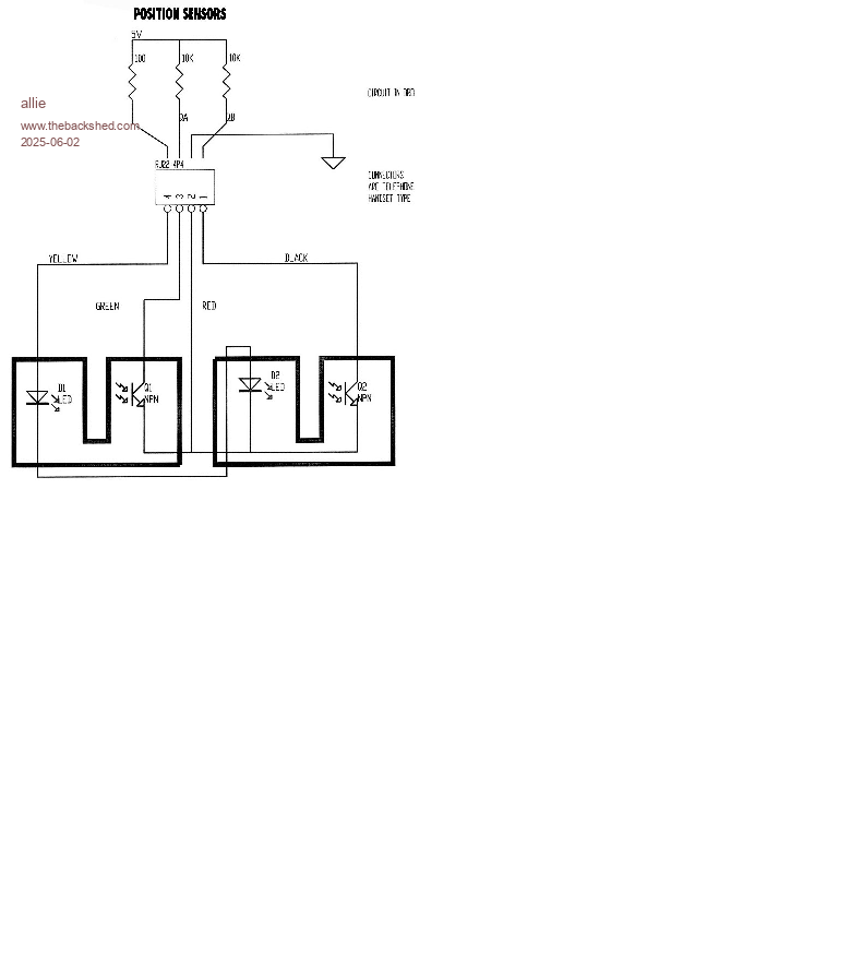 Is this encoder quadrature regards Allie Edited 2025-06-02 00:25 by allie |
||||
| allie Regular Member Joined: 06/10/2018 Location: CanadaPosts: 88 |
The encoder produces .100" (100/1000") in one revolution. I tried the y axis movement to its maximum distance of 7" at its highest speed of 25 and the count was 14,001, the PicoMite had no problem counting the movement. Thanks to every one for your input. Allie |
||||
| PhenixRising Guru Joined: 07/11/2023 Location: United KingdomPosts: 1960 |
Makes no sense. The diagram shows the phase offset and the quad decode responds to all four transitions. Something doesn't add up. Do you have a spec sheet for the encoder? |
||||
| allie Regular Member Joined: 06/10/2018 Location: CanadaPosts: 88 |
I searched the DRO encoder on the web and I couldn't find any specs, so I counted the teeth on the wheel that turns in between the two sensors and it has 25 teeth on it. where there is 25 teeth and 2 sensors shouldn't the count be 50/1000 instead of 100/1000. Allie |
||||
| phil99 Guru Joined: 11/02/2018 Location: AustraliaPosts: 3293 |
Now we are getting somewhere. you can get 2 counts per tooth with leading and trailing edges. The 90° offset between sensors (from the perspective of a tooth, not the wheel) gives a total 4 counts per tooth. In the motor specifications "Stepper Motor 100 oz-in, 2 Amp, #23 Frame size, 400 steps per revolution" they are probably talking about the same kind of steps. That is each phase probably has 100 poles, which does not match the 25 you found on the encoders. If the motors have 100 poles / phase your encoders then only have 1/4 of the specified resolution, reducing their usefulness. Recording both phases from the motor drive will give the same quadrature signal as the encoders but with 4 times the pulse count per inch. |
||||
| Volhout Guru Joined: 05/03/2018 Location: NetherlandsPosts: 5931 |
Yes, that looks like 25 teeth... 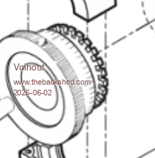 In essence your motors have more resolution than the encoders. Depends on what you are trying to achieve that encoders may not be useful for accuracy in CNC, but can be used to detect of an axis is stuck. Volhout PicomiteVGA PETSCII ROBOTS |
||||
| allie Regular Member Joined: 06/10/2018 Location: CanadaPosts: 88 |
When I checked the count on the y axis with the table moving to it maximum distance of 7" and the count being 14,001 which is double the 7,000. (7" is equal to 7000/1000) my machine is in inches so 1" = (1000/1000). Divide the 14,001 by 2 = 7,000.5 that is close enough for what I want to do. An error of 1/2 of a thousand in 7 inches. Regards Allie |
||||
| allie Regular Member Joined: 06/10/2018 Location: CanadaPosts: 88 |
Hi all, I'm trying to use the serial console with Tera Term on the CMM2 Gen2 (on windows 10) when I start tera term it say cannot find com3 when I go into tera term setup and go to serial port it list com4 next port com5 and next port com6 when I change between the 3 USB ports on my laptop. Do I need com3 or Do I need to set up CMM2 Gen2 for serial console because last year I used the CMM2 Gen2 with a keyboard and VGA monitor. Regards Allie |
||||
| phil99 Guru Joined: 11/02/2018 Location: AustraliaPosts: 3293 |
In the old CMM2 User Manual under "Power & Serial Console Connector" are instructions on how to connect, including this:- That will tell you which port to use. And this:- I imagine the Gen2 is similar. |
||||
TassyJim Guru Joined: 07/08/2011 Location: AustraliaPosts: 6538 |
Start TeraTerm Try to connect to serial and note the ports listed. plug the CMM2 in in TeraTerm, try a new connection and see what serial ports are listed. The new port that wasn't there the first time is the CMM2. VK7JH MMedit |
||||
| allie Regular Member Joined: 06/10/2018 Location: CanadaPosts: 88 |
I tried to get the CMM2 Gen2 going on tera term with no luck. But I got the CMM2 Gen2 Version 2 running. I will try the CMM2 Gen2 later as I have to get ready to go to work now. Regards Allie |
||||
| The Back Shed's forum code is written, and hosted, in Australia. | © JAQ Software 2026 |
