
|
|
Forum Index : Microcontroller and PC projects : Proto Board for the uMite 28
| Author | Message | ||||
| Zonker Guru Joined: 18/08/2012 Location: United StatesPosts: 772 |
Yep... I couldn't get it to fit just right, so I ended up with this way. I was trying to avoid the vias because silk doesn't print over any kink of hole objects... Anyway, I just hope the Itead guys get the updated files OK... Damm... I just knew I would somehow screw this up..!  (my bad) (my bad)
I think things are looking OK from what I can see see using the online viewer... Thanks Grogster for you time buddy..!! |
||||
Grogster Admin Group Joined: 31/12/2012 Location: New ZealandPosts: 9975 |
Ahhhh - I see. That's fine then. Ignore me. 
You are most welcome - not a problem.  Smoke makes things work. When the smoke gets out, it stops! |
||||
bigmik Guru Joined: 20/06/2011 Location: AustraliaPosts: 2981 |
Gday Zonker, Only a minor thing, I notice that the bottom silk screen overlay has download spelt with a U instead of a W... Not worth changing of course unless you do a new artwork for other fixes. Did iTead give you an estimate on lead time? Regards, Mick Mick's uMite Stuff can be found >>> HERE (Kindly hosted by Dontronics) <<< |
||||
| Zonker Guru Joined: 18/08/2012 Location: United StatesPosts: 772 |
Good evening Mick... I did get one message from them: Thank you for choosing our PCB prototyping service. We have received your gerber files and the files have been submitted to the factory for auditing. During auditing, if there are any problems or have questions about your design, our colleagues will contact you via E-mail. If auditing passes, factory will arrange production within 24 hours, and usually we need 4-5 days to finish the entire PCB production process. If everything goes well, you will not receive any notification via E-mail. After the board is finished, we will need 1-2 extra working days to deal with packaging and delivery. After the parcel is sent out, we will update the order status and inform you of the track number and tracking method via E-mail. But, so far that's been it... I think it's going on a week now... Hope not to much is wrong... I think the last set of files I sent was ok... Not sure what's up... Maybe another E-mail to them is due... |
||||
| Geoffg Guru Joined: 06/06/2011 Location: AustraliaPosts: 3362 |
The next thing that you will get is a shipment notification (unless there is a fault in your gerbers). Geoff Geoff Graham - http://geoffg.net |
||||
| Zonker Guru Joined: 18/08/2012 Location: United StatesPosts: 772 |
Man.. I hope everything goes well.. BTW... How many do you and Mick want.. got 100 ordered, with 30 sets of the FTDI chip and USB con's.. Do you guy's think doing a 44 pinner in this board type format is worth the effort..? I already have it half laid out and it seems like it's going to fit into the same board size as the 28 pinner.. I could post it and see what everyone thinks... |
||||
| bigmik Guru Joined: 20/06/2011 Location: AustraliaPosts: 2981 |
Hi Zonker, I, personally, only want about 6 at this stage (1 or 2 will be for Don who is enjoying a month long cruise at the moment)... I will probably take more if you are stuck with them as I certainly dont want your efforts to cost you $$$$. Of course pending demand I will get less if that means more available for others.. I assume you got the PM with my address details? I am happy to re-ship PCBs in Aus to other customers if that makes it cheaper/easier for you.. Although USPost (international) is probably about the same as AUS post (local), and it may be easier to ship directly.. Whatever you prefer I will work with. Regards, Mick PS. As for the 44pinner.. I am interested but not as excited by that as I am with the 28pinner.. I know white wizard has a PCB on the way so maybe if you are happy with his layout then we have one of each already, just if you want to maintain a standard size for stacking etc.. Mik Mick's uMite Stuff can be found >>> HERE (Kindly hosted by Dontronics) <<< |
||||
| MicroBlocks Guru Joined: 12/05/2012 Location: ThailandPosts: 2209 |
@Zonker, Not getting an e-mail is actually good news, it then probably is in production or already produced. I would give it 2-3 days more. I would be interested in about 10 pieces. Also some bare PCB if that is possible. Microblocks. Build with logic. |
||||
| WhiteWizzard Guru Joined: 05/04/2013 Location: United KingdomPosts: 2991 |
All, I have been in touch with Zonker by PM regarding iTead. We both placed our orders with iTead about the same time and we are both now playing the waiting game. Hopefully we will hear from them next week informing us of shipment. I ordered 40 PCBs from them for the 44 pin TQFP Eval Module. I will update you all as soon as I hear from iTead . . . . Regards, Phil |
||||
| Zonker Guru Joined: 18/08/2012 Location: United StatesPosts: 772 |
Thanks Gents for the reply... Will let everyone know then things are moving... |
||||
| isochronic Guru Joined: 21/01/2012 Location: AustraliaPosts: 689 |
I think the 44 pin mx have pin similarity to the pic24 and dspic33 relatives - so the chances are, there are many pcbs that can be used. Don't know which i/o pins are used by micromite for comms etc though. I have a few surplus 2x3" pcbs that have the 44 pin layout for a dspic33 '804 connected to 3.3 v and most b pins etc, if anyone wants one |
||||
| Zonker Guru Joined: 18/08/2012 Location: United StatesPosts: 772 |
OK... The uMite 28 pinner prototype boards have Shipped...!! (sweet)... |
||||
| WhiteWizzard Guru Joined: 05/04/2013 Location: United KingdomPosts: 2991 |
How dare they stopped working on my 44pin TQFP PCB to get your one out first  |
||||
| Zonker Guru Joined: 18/08/2012 Location: United StatesPosts: 772 |
Good evening Gents.. Well, it looks like a registered mail was attempted at the house today from Hong Kong.. Nobody home as we were both at work... So, I will stop by the post and pick them up on the way to work tomorrow.. (finally).. Already had a talk with Lou about dropping by on Saturday to see if we can get a few put together during the weekend... Should know something soon... |
||||
| Zonker Guru Joined: 18/08/2012 Location: United StatesPosts: 772 |
Good morning Gents..! Sorry for being a "ghost" all weekend, it was a busy one.. Had to visit my Mom in the hospital and hang out with my brother Chris on Sunday to celebrate his birthday... (yes, there was a few beers involved) Anyway.. Thanks to the fine work and time that Lou Cassady put in this weekend, I think we can report that the uMite-28 pinner proto-board seems to be functioning OK... I have not tested the Rs-485 transceiver part yet, but hopefully will get this done later in the week... At work this week, we will be finishing the system testing of a 450kw switchmode inverter unit for the company. (Bitrode Corp.) So it going to be a busy week.. (I will try not to get killed off.!) So, anyway, I wanted to forewarn anyone who wants to get these boards that trying to solder on the FTDI USB chip is going to be a "Royal Bitch"..! I tried to get one soldered on while at Lou's house on Saturday, but couldn't get it done.. I was holding it down with very thin tape and giving it a go, but as soon as I got some liquid flux on it, it would "unstick" the tape..! Damn.. After 2 hours of trying.. I gave up on it..!! fortunately, there is a guy, (Jean at work, who works in the PCB dept.) managed to get 2 of the USB chips on Friday before testing during the weekend... To further complicate this, there seems to be a slight registration problem with the device footprint also that I noticed a Lou's house while looking at it with his video microscope. I had used a DFN-10 footprint I got online and modified it into a DFN-12 package for use in the design. At the time, I didn't have any USB chips to check it with... I will talk with Jean this week about getting more of the USB chips soldered on he boards. He is good at doing SMD work and we have a nice workstation microscope there... I have not worked up the pricing on this stuff yet, but don't worry, I don't want to be making any money on this deal, I was just trying to help promote the uMite project and the fine work done by Geoff and many others here on the Shed... Nuff for now... More info coming soon... |
||||
| WhiteWizzard Guru Joined: 05/04/2013 Location: United KingdomPosts: 2991 |
Good to hear progress from you & Lou. 
If you PM me I will let you know how I hand solder SMDs with 100% success and also a rather neat & tidy finish. It may be the technique you're currently using, but if not then you will definitely find the info very helpful. And like anything, once you know how, it is really simple (and impressive!!). Don't work too hard . . . |
||||
| bigmik Guru Joined: 20/06/2011 Location: AustraliaPosts: 2981 |
Great News Zonker, I dont mind you adding some beer money for yourself... You deserve it. Looking forward to some details via PM Regards, Mick Mick's uMite Stuff can be found >>> HERE (Kindly hosted by Dontronics) <<< |
||||
| bigmik Guru Joined: 20/06/2011 Location: AustraliaPosts: 2981 |
Gday Zonker, Hope your mum is doing OK and will be out of hospital soon. As for your brother.. at least there was BEER
Does the registration problem look like this composite I did from the data sheets and your overlay? 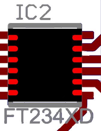
If so I see the problem and the chip is only 3mm square.. Real bummer to do that one.. If you run into strife I will have a go for mine (if you have spare chips to sell) but it would probably make my eyeballs implode even with Maggy light and microscope.. You will need a super pointy tip for your iron. Dont sweat on it though I am sure we will get over that problem. Any Photos? I cant wait to get them now. Regards, Mick Mick's uMite Stuff can be found >>> HERE (Kindly hosted by Dontronics) <<< |
||||
| MicroBlocks Guru Joined: 12/05/2012 Location: ThailandPosts: 2209 |
Why does that drawing stir some memories...... 
Happens to everyone i guess. Nothing to worry about though as it is still manageable. I got good results by putting a little solder on the islands first, then added some flux and held the part in place while reflowing the solder on two corner pins. The rest was just a drag along the pins to finish it. With some practice it goes reasonably quick. Microblocks. Build with logic. |
||||
| bigmik Guru Joined: 20/06/2011 Location: AustraliaPosts: 2981 |
TZ, Yes, it does bring back memories... My common mistake is 0.20" spacing on caps that have 0.10" pins and vice versa.. 
The problem with your solder method quoted above is that the FT234XD chip is a square chip with no pins as such, they are 'LANDS' up the side of the chip and will be quite tough to solder when they are offset.. Tough! Not impossible... Regards, Mick Mick's uMite Stuff can be found >>> HERE (Kindly hosted by Dontronics) <<< |
||||
| The Back Shed's forum code is written, and hosted, in Australia. | © JAQ Software 2026 |
