
|
|
Forum Index : Microcontroller and PC projects : *** COMM *** Mick�s PCB offerings
| Author | Message | ||||
bigmik Guru Joined: 20/06/2011 Location: AustraliaPosts: 2981 |
@Jim, I had to borrow it from my daughter... Now if I can sell one I can pay her back.  Mick's uMite Stuff can be found >>> HERE (Kindly hosted by Dontronics) <<< |
||||
| Phil23 Guru Joined: 27/03/2016 Location: AustraliaPosts: 1667 |
Only just spotted this thread after it's Bump. I do occasionally weld the lids on hard drives. Inverter Welder, usually set at about 120 amps. 3.2mm rods & just one decent tack in the top cover. Think it's probably enough to ensure the clients data doesn't escape from the rubbish tip. Usually do then in batches of a dozen or so with drives from discarded PC's. Cheers. |
||||
| MicroBlocks Guru Joined: 12/05/2012 Location: ThailandPosts: 2209 |
Should SCK not be SCL for the I2C bus? SCK suggests it is a SPI pin. At least that is how i name the pins. (Sorry that i did not notice it sooner.  ) )
Microblocks. Build with logic. |
||||
jman Guru Joined: 12/06/2011 Location: New ZealandPosts: 711 |
@Jim That is how the LCD is labeled does seem odd thou A picture speaks a thousnad words 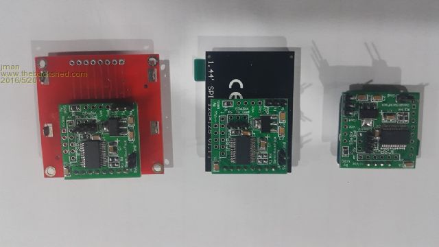
Regards Jman |
||||
| bigmik Guru Joined: 20/06/2011 Location: AustraliaPosts: 2981 |
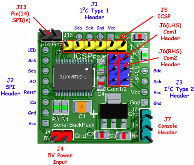
@MicroBlocks, I know what you say, but realistically Sck and Scl mean the same in my mind SERIAL CLOCK, and as Jim says that is what the modules themselves are labelled. I understand that the Sck on the I2C header is NOT the same pin as the Sck on the SPI header in fact I make mention of the pin No's in the manual as the unused port is available for General IO if anyone wants to use the Serial BackPack stand alone. On such a small and relatively compact board it is very difficult to get a good clean SILK SCREEN especially in the real life board... I have had to use 0.05" text in many places.. I really don't think anyone would confuse the two headers (mainly due to the differing number of pins) and all headers are labelled as i2c or SPI.. However, If I get a re-run I will change the label as, despite that being what the displays have printed, I prefer Scl myself. Kind Regards, Mick Mick's uMite Stuff can be found >>> HERE (Kindly hosted by Dontronics) <<< |
||||
plover Guru Joined: 18/04/2013 Location: AustraliaPosts: 306 |
I am struggling very hard to keep up with developments. I have scanned through the pdf file and looked at the schematic. I am actually interested in using it stand alone I need one digital output one or two more would be added bonus. I am a bit lost as to difference between 'console' and the com1/2 ports. How would I connect my laptop (assuming MMBasic is loaded)? I would have RS232 connector on some of those. |
||||
| jman Guru Joined: 12/06/2011 Location: New ZealandPosts: 711 |
Hi Com2 is unused so you can use those pins for I/O (Pins 9 and 10) You would connect your laptop to the console port via a TTL serial adapter The serial input for the LCD display is also at TTL levels (3.3v of course) on com 1 only the rx is required. If you use an I2C LCD then pins 3 and 25 will also be available for I/O One more pin 21 can be used if you change the code to use the SerialRX CFunction (included in firmware download) Regards Jman |
||||
| plover Guru Joined: 18/04/2013 Location: AustraliaPosts: 306 |
jman Thank for information. Together with readin the 'manual' again I think I am getting it. I believe I have some RS232 to ttl adapters which I was going to use on a modem that requirted backport access (not got around to do this either yet). I am not sure they had 3.3V though. The main thing is that I will need this adapter piece and USB probably better choice. |
||||
| bigmik Guru Joined: 20/06/2011 Location: AustraliaPosts: 2981 |
GDay Plover, It looks like Jman has set you right with the Console. But if you look at the following extract from the manual: 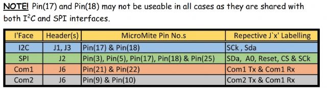
Assuming you are using an OLED display on the I2C port you would then have the following to reallocate as General IO pins. (assuming you are not going to use the ports for other uses) Com1 Tx Pin(21) Com1 Rx Pin(22) Com2 Tx Pin(9) Com3 Rx Pin(10) SPI SDa Pin(3) SPI A0 Pin(5) SPI SCk Pin(25) That gives a total of 7 General IO pins available for use in a stand alone environment. Only 4, the Com1 and Com2 pins, if you are using the SPI header. Kind Regards, Mick Mick's uMite Stuff can be found >>> HERE (Kindly hosted by Dontronics) <<< |
||||
| plover Guru Joined: 18/04/2013 Location: AustraliaPosts: 306 |
bigmik Thanks, I knew I tried to read the manual too fast. I do better in small doses, I should be better off in a couple of months when other jobs have settled down/completed. One task that I underestimated involved rudimentary teaching Windows 7 Tablet and Windows 10 Notebook operation to our widow next door. I have basically given up on windows, well now I am having a crash course. ( added UB Keyboard and mouse for the moment to speed up things) Ordered BlueTooth Mice. I am having none of the touch panels, too old for that. Having looked a bit further your USB-TTL seems a better option, I am putting it on the list. Will email you later in the week. |
||||
| bigmik Guru Joined: 20/06/2011 Location: AustraliaPosts: 2981 |
GDay All, I have just finished testing MuP V3 and I am very happy with it and it is now available if anyone is interested. The most significant difference from Ver 2 is the addition on a PIC16F1455 loaded with MicroBlocks Serial-TTL/Programmer code. This chip (I called MB chip) will do the USB-TTL serial conversion (eliminating the need for a separate board or cable and will also act as a Programmer to program the PICMX170 with a new HEX file, using PIC32PROG (a freeware program). This chip will be available from MicroBlocks directly or through myself as I have an agreement with Microblocks to distribute these directly. 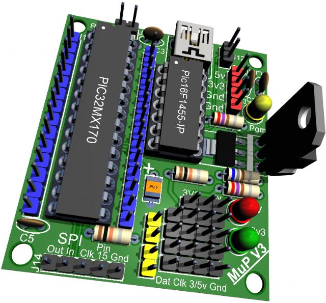
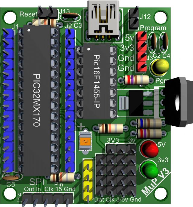
The main differences from MuP Ver 2 (which will still be available) are: 1. MuP Ver.3 may now be built entirely using through-hole components. The only SMD components are the VCap (which I have added two THP pads to use a standard Tantalum if you chose to do so) and VReg 1 (which may be substituted by a TO-220 version, in the VReg 2 position). NOTE!! Do NOT install both VRegs as that will cause instability of the power supply. 2. Removed the option for a USB-TTL cable as the on-board MB chip does that function for you. 3. Added a 5 pin SPI header interface. 4. Added a Reset header. 5. Added a Pgm header. (see details later in this document) 6. Added a Pgm LED. (see details later in this document) 7. Added support for the MB chip. 8. Added a mini-USB (THP) connector. The Bare PCB will be available for $3Aus (roughly $2US) ea and I am offering the MB chip at $8Aus (roughly $5.50US). I will post a purchase link as soon as Don gets time to add it to my site. Micks `Site' Regards, Mick EDIT ***
There is one minor error on this board in that pin 8 of the PICMX170 is not connected to GND, generally this is not a critical problem as Pin 8 is connected internally to Gnd but the next batch will have this connected.. To fix this a simple 10mm lenth of wire on the underside of the board to pin19 or the PIC chip will correct it.. I will add a note to this effect with any purchase of affected boards. Mik Mick's uMite Stuff can be found >>> HERE (Kindly hosted by Dontronics) <<< |
||||
| bigmik Guru Joined: 20/06/2011 Location: AustraliaPosts: 2981 |
Hi All, I have added the manual and other support documentation to the Doc-register. Doc-Register MuP. Ver 3 Kind Regards, Mick EDIT *** Don has added the MuP. Ver 3 to My `Site' Here is the direct link to MuP Ver. 3 Kind Regards, Mick Mick's uMite Stuff can be found >>> HERE (Kindly hosted by Dontronics) <<< |
||||
| bigmik Guru Joined: 20/06/2011 Location: AustraliaPosts: 2981 |
Hi All, I have discovered a (relatively) minor issue with Serial BackPack Version 1. The pullup that should go to Pin 1 of the Pic chip in actuality goes to Pin 2 by mistake. For some reason this does not seem to impact on the operation or reliability of the board in any way.. I assume that the MCLR line must have its own internal pullup.. As Pin(2) is unused it is safe to simply short Pin(1) and Pin(2) on the pic chip if you want to be certain that the MCLR has a correct pullup installed.. As a consequence I am no longer offering Serial BackPack Ver. 1 as a product.. I have left 4 x slabs of 9 (see below) that I am prepared to offer for $5 per slab if anyone wishes to have them. Postage will be $3 overseas or $1 in Australia. Full details of the board is on my site Serial BackPack The `slab' 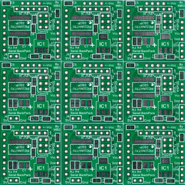
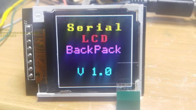
This has not been a total disaster as it has gently encouraged me (like a poke in the eye with a sharp stick) to redo the Serial BackPack and as a consequence I have been able to offer a much better design functionality wise with more IO available in a stand-alone environment.. (full details after I can get time to build and test my Ver. 2) Sample picture shown below.. 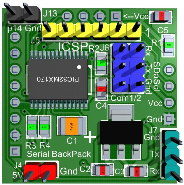
Kind Regards, Mick Mick's uMite Stuff can be found >>> HERE (Kindly hosted by Dontronics) <<< |
||||
| matherp Guru Joined: 11/12/2012 Location: United KingdomPosts: 11668 |
Big shout out for Mick's V2 Serial backpack. This clever little board interfaces directly with a whole range of displays without any additional wiring and has lots of extra pins free for interfacing with the usual range of sensors etc. This makes it perfect for many small scale measuring and monitoring applications. Note how you can't see the PCB behind the displays it is so small and neat. ILI9163 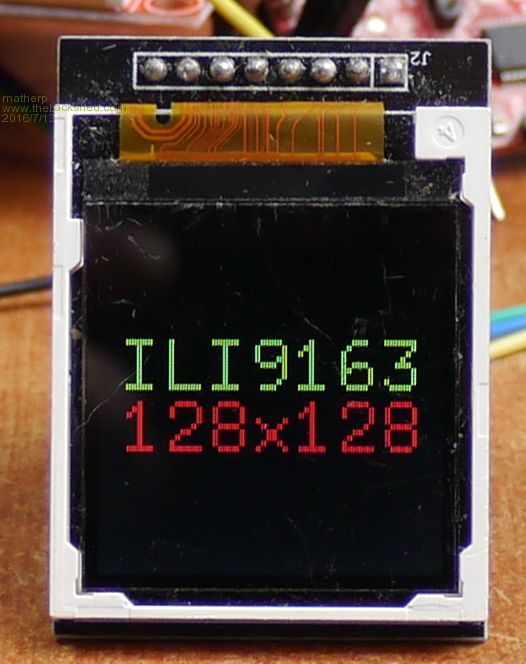
ILI9341 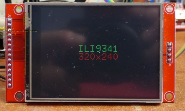
TM1637 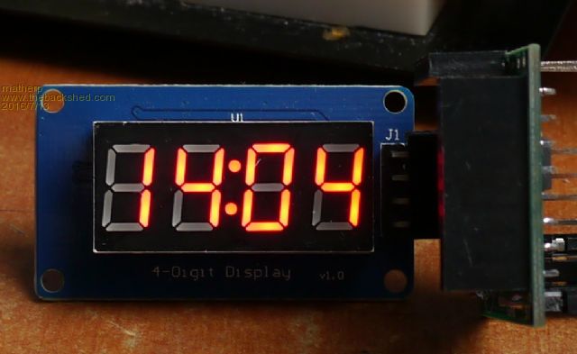
SSD1306 shown here face down with the PCB mounted to it. NB the version shown is actually the 1.3" variant not the 0.96" version linked which is exactly the same size as the backpack 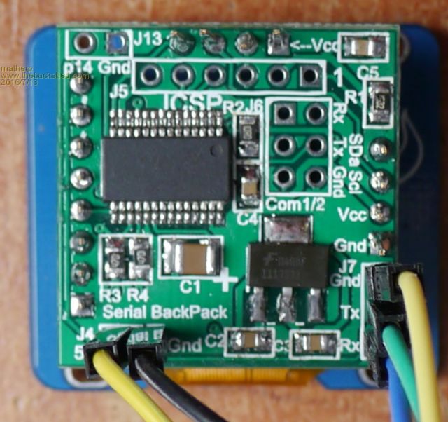
ST7735 Note, the version linked has the correct pinout. Other versions have the pins differently arranged and won't mount directly. 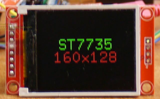
Nokia5110 Note, the version linked has the correct pinout. Other versions have the pins differently arranged and won't mount directly. 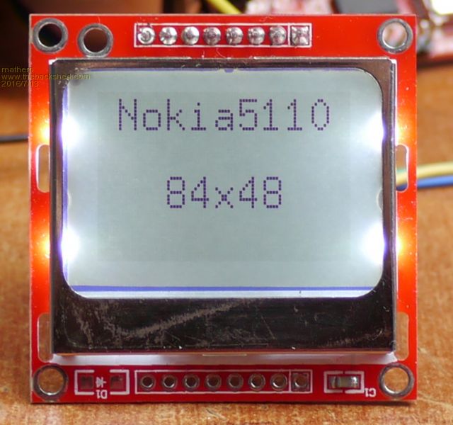
|
||||
| bigmik Guru Joined: 20/06/2011 Location: AustraliaPosts: 2981 |
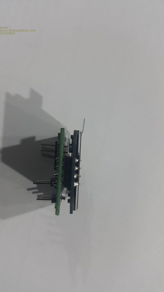
Thank you Peter, Those pictures are great and your praise is high. I have finished the manual for Serial BackPack Version 2. Full details are available - HERE! - Serial BackPack Version 2 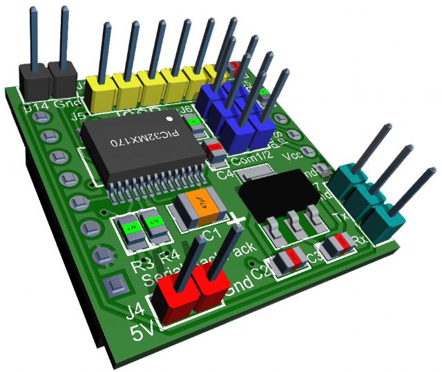
This board is approximately 27.5mm x 27.5mm (1.08" x 1.08") in size (see image below showing actual size in comparison to my MuP.) 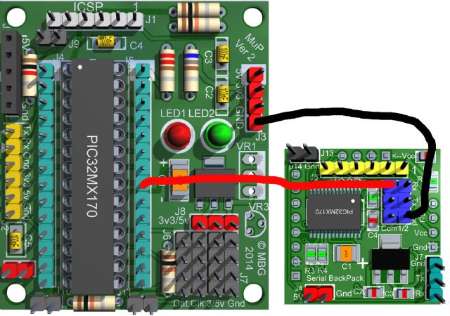
Serial BackPack Version 2 fixed a minor problem on Version 1 (now superseded) and I have re-allocated some different IO pins to create better flexibility as a controller in its own right, Thank you very much to Peter for assistance and continual poking with a pointy stick until I got the message 
Here is a list of the IO connections so you can see what pins are available for each connection. 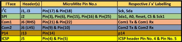
I have kept my prices the same as the Version 1, full details of all my products and pricing may be found on my site located ---> HERE <--- Kind Regards, Mick Mick's uMite Stuff can be found >>> HERE (Kindly hosted by Dontronics) <<< |
||||
| bigmik Guru Joined: 20/06/2011 Location: AustraliaPosts: 2981 |
Hi All, Here is another small board to add to my list of offerings. MuP-Proto As its name suggests it is a Prototyping shield designed to plug into either MuP (slightly offset) or MuP-3 (exactly aligned) and allows a few small components to be soldered to it in a breadboard fashion and connect directly to a MicroMite '170 (MuP). 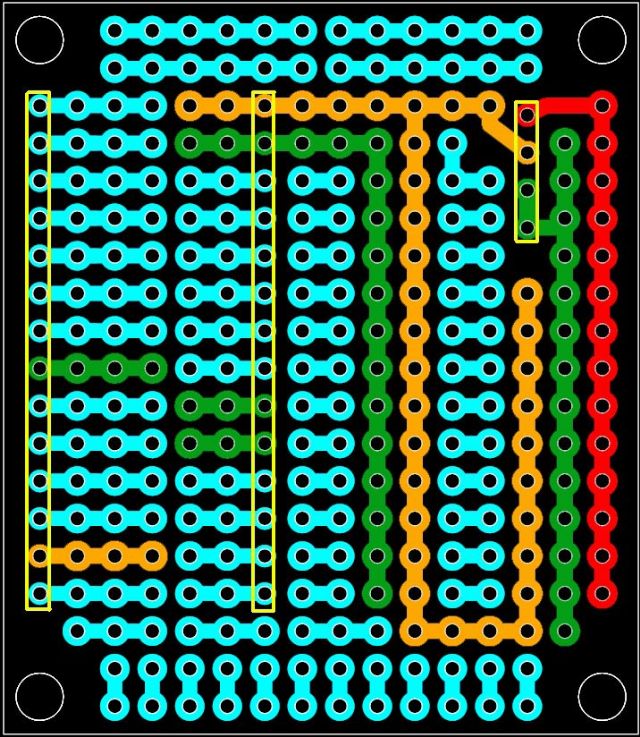
The above picture shows the GND (in GREEN), 5V (in RED) & 3v3 (in ORANGE) power rails 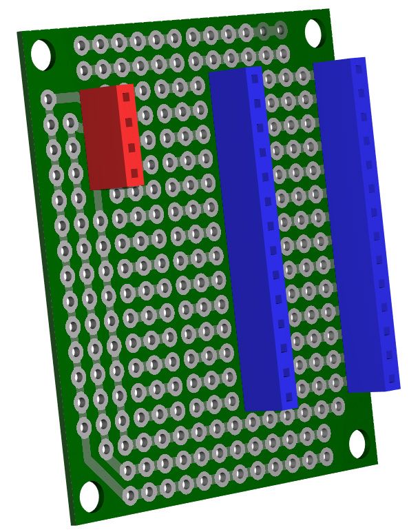
This picture shows MuP-Proto with female headers fitted to mate up with MuP. 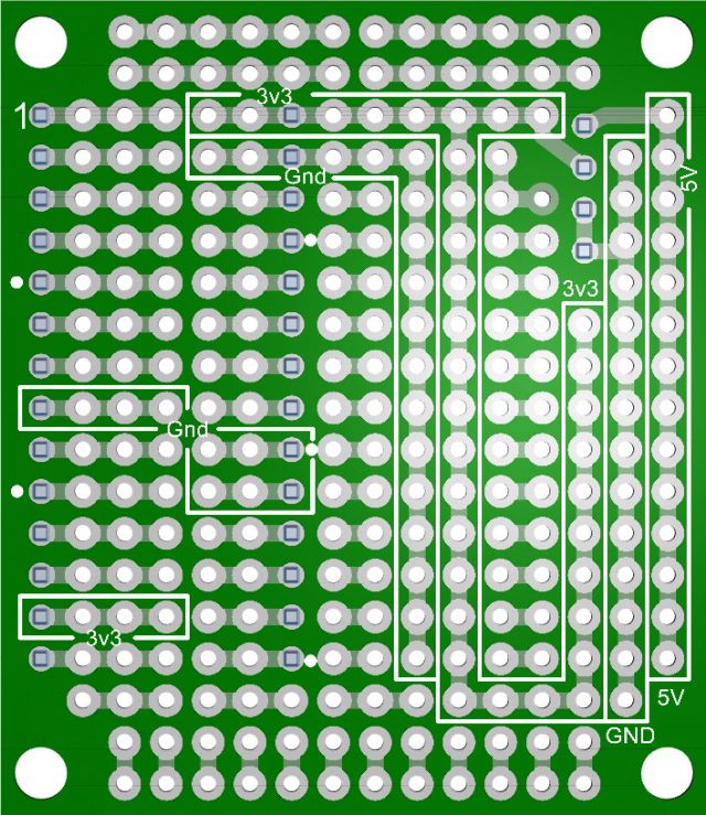
I have priced these at $3each plus postage ($1 in Australia, $3 rest of the world) those prices will be fine for up to 6 boards packed into an envelope.. Kind Regards, Mick. Mick's uMite Stuff can be found >>> HERE (Kindly hosted by Dontronics) <<< |
||||
| WhiteWizzard Guru Joined: 05/04/2013 Location: United KingdomPosts: 2991 |
Nice little board there Mick - extremely useful 
WW PS: Please can you arrange a 'Pigeon' with an equal split of these and MuP3's. No rush . . . 
|
||||
| bigmik Guru Joined: 20/06/2011 Location: AustraliaPosts: 2981 |
Thank you Phil, A pigeon has been released and is on its way to you. I have added a new little board I think you might like that I havent `officially' released yet. My PicoMite.. slightly larger brother to the NanoMite at 15mm x 19mm. 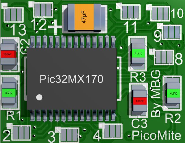
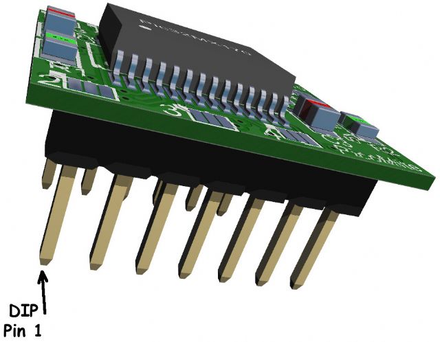
Kind Regards, Mick Mick's uMite Stuff can be found >>> HERE (Kindly hosted by Dontronics) <<< |
||||
| WhiteWizzard Guru Joined: 05/04/2013 Location: United KingdomPosts: 2991 |
Thanks Mick. One issue though You're gonna have to rename the Nano to Pico, and your new unit (which is bigger) to Nano(2) |
||||
| lizby Guru Joined: 17/05/2016 Location: United StatesPosts: 3829 |
Mick, Thanks very much for your MuP work. I am very happy with my 2 MuP3s, but found a problem on the second one which I thought I'd share in case anyone else encountered it. I2C did not work as it had on the first one. I tracked it down to Dat not being pulled up. Turned out the jumpered pin connected to the top Dat pin was not connected. I retouched the solder on the pins and still no luck. I soldered a link, but then the 3 lower pins were not pulled up. I soldered a link to the second from the top, and all is fine. Of course, the top of the board is covered with header pins, so I can't examine it. Perhaps the through-hole plating was deficient, or perhaps I did something while soldering it in the first place. Hope this may help if someone else is baffled. PicoMite, Armmite F4, SensorKits, MMBasic Hardware, Games, etc. on FOTS |
||||
| The Back Shed's forum code is written, and hosted, in Australia. | © JAQ Software 2026 |
