
|
|
Forum Index : Microcontroller and PC projects : Explore64 (Geoff’s MM+ module)...
| Author | Message | ||||
| WhiteWizzard Guru Joined: 05/04/2013 Location: United KingdomPosts: 2991 |
@Bryan1 So you got touch working now?? |
||||
bigmik Guru Joined: 20/06/2011 Location: AustraliaPosts: 2981 |
GDay Bryan, I havent yet got a 470 up and running so I cant offer much advice.. You do have the pullups on the Clock and Data lines on the DS1307 don't you? Also I assume DS1307 is a valid clock chip (not checked that yet) Mick Mick's uMite Stuff can be found >>> HERE (Kindly hosted by Dontronics) <<< |
||||
Grogster Admin Group Joined: 31/12/2012 Location: New ZealandPosts: 9975 |
@ Bryan: You have to OPTION LCDPANEL DISABLE, then cycle power, then OPTION LCDPANEL.... for the new setup, then cycle power again. At that point, you should be running with the new settings. Simply issuing a new OPTION LCDPANEL.... command does not seem to work, and you have to clear the settings from the MM first by way of the disable command. That done, you should not have any issues. With SPI LCD's, double-check you have the clock-line for the touch controller, on the correct pin, as I managed to get that wrong last week, and I was left scratching my head for quite a while till I realized what I had done wrong - I was getting the same errors in that the touch failed to correctly calibrate, but despite the touch clock line being effectively disconnected, the GUI CALIBRATE command still worked OK, which is what really threw me..... Smoke makes things work. When the smoke gets out, it stops! |
||||
Bryan1 Guru Joined: 22/02/2006 Location: AustraliaPosts: 2099 |
G'day Guy's, still trying to get the lcd working, got had a 22ohm resistor connected to the 5V rail and it was pretty bright but trying the gui test display just shows the backlight going a bit jittery, so put the resistor on the 3v3 rail and its the same thing on the test display. Tried 51,53,54 on the lcd lines,, no change so now just tried 3,2,1 and still the same. Mick yes I have a couple of 4K7 pullups connected to the V+ pin, now on the third and last ds1307 and they do act like clones. I madeup a crude backup battery by soldering on some pins to the + on one and another pin on the - then taped them together with friction tape. The voltage is 2.85 volts so one would think that would be enough to keep the the time going eh. I set the time and checked it for 3 minutes then shut the board down for 2 minutes. When I checked the time it has advanced 20 seconds. Edit: Eh Grogs thanks for that tip mate just did it and tried the gui test display and YAY bright bubbles everywhere on the screen. The RTC is now 11 minutes behind since I set it and that battery is showing 2.89 volts so I am wondering if the backup battery is under 3 volts would that throw the time way off Second Edit: Ok the touch wasn't calibrated so got the calibration going but it wouldn't go off the first one so cancelled it. The pins I was using were Tcs 17 and Tirq 16, got the error pin 16 was in use so changed it to pin 15, tried the option touch 17, 15 and got that endless error loop again. time to reflash again |
||||
| Grogster Admin Group Joined: 31/12/2012 Location: New ZealandPosts: 9975 |
GUI - Yeah, SPI LCD screens should change from white to a light grey on startup, which indicates correct initialization. If the LCD does NOT turn light-gray on power-up, then the screen has not initialized correctly. 2.89v is pretty close to 3v, and the battery consumption from the RTC chip is microamps, so it should be fine - others will let you know their thoughts on that. I think I remember reading somewhere on this thread that you were using a 1307 RTC? They are very drifty, and PERSONALLY, to be avoided, but that is just me. Having said that, even a drifty 1307 would not drift that much in such a short time, so something not quite happy there. EDIT: Did you OPTION TOUCH DISABLE before you tried to set the new pins? Gotta do that, or the MM keeps trying to use the old pins, and setting duplicate ones obviously causes the MM+ to throw a wobbly. This may even be classified as a bug by Geoff - we'll see if he chimes in on this topic here. Smoke makes things work. When the smoke gets out, it stops! |
||||
| Bryan1 Guru Joined: 22/02/2006 Location: AustraliaPosts: 2099 |
Hi Grog's, Yes you are right I DID forget to do option touch disable so that is what could of thrown the wobbly. Now after the reflash got the touch calibrated and the test display working along with the customary "hello Bryan ya dork" on the screen. But when I did a rtc gettime guess what RTC not responding. Those chips are going back to Aztronics when I'm down the hill later this week and I will get a refund as they are crappy clones. I do have an old pcf8563 rtc in the shed so I'm off to get that now. Cheers Bryan |
||||
| Grogster Admin Group Joined: 31/12/2012 Location: New ZealandPosts: 9975 |
I am afraid I don't think I have any 1307's to test, but I do have some 3232's, which I will try in just a sec to see if they co-operate OK. I did some lengthy testing with EEPROM's on I2C just as Geoff was releasing the beta, and they appeared to work fine, however, there could be an issue with the RTC's. Has anyone else here had RTC issues with the new beast? Smoke makes things work. When the smoke gets out, it stops! |
||||
| robert.rozee Guru Joined: 31/12/2012 Location: New ZealandPosts: 2528 |
bryan: you are aware that the DS1307 requires 5v connected to Vcc and 3v connected to Vbatt, yes? if you have Vcc connected to a 3v3 supply, the device will not work, as the I2C bus is locked out until Vcc reaches 1.25 x Vbatt (1.25 x 3 = 3.75v). you may be able to connect pin 2 (X2) to one of the micromite frequency inputs to measure the 32kHz clock frequency. if this doesn't work, you'll need to configure pin 7 (SQW) as a frequency output. as an aside, if SQW is configured as a output, it may be possible to measure the period or frequency of this pin and use the result to derive a clock trim value (as being discussed elsewhere). cheers, rob :-) |
||||
| Grogster Admin Group Joined: 31/12/2012 Location: New ZealandPosts: 9975 |
I have a 3231 hooked up, but the RTC commands do not seem to be working for me. I can RTC SETTIME and RTC GETTIME, but the results are not saved or loaded. Example: RTC SETTIME 15,07,28,23,07,00 - this command completes fine. Remove power and replace. RTC GETTIME completes fine, then ? time$,date$ results in the default power-up date and time: 00:00:30 for time, and 01:01:2000 for date. If I remove the SDA and SCL lines and issue the same commands, I get the standard error: "Error: RTC does not respond.", so I think that the MM+ can see the RTC chip, but something is going wrong with the commands. So, RTC commands are not working on this module - can anyone else with an RTC please check and confirm this? ...we might have a bug here... I will hook up my logic analyser and check the signals. EDIT: OK, the I2C is going out, but the MM is not updating the RTC when you issue a RTC GETTIME. Logic GIF #1(read) Logic GIF #2(write) Smoke makes things work. When the smoke gets out, it stops! |
||||
| Bryan1 Guru Joined: 22/02/2006 Location: AustraliaPosts: 2099 |
G'day Guy's, I do have a scanalogic module here so tomorrow i'll go setup the BB in the shed and go do some checking. One thing I did find after a reboot the lcd has stopped working too, tried a gui test display and got nothing on the screen. Anyway enough for today so more fun in the morning getting my head around the syntax as I keep getting it wrong. Cheers Bryan Robert yes after my first few attempts I went and downloaded the datasheet and RTFM then learnt I did need to run the rtc on 5 volts so got that setup. Got a pcf8563 installed now so I'll see how that goes over night. |
||||
| Grogster Admin Group Joined: 31/12/2012 Location: New ZealandPosts: 9975 |
Interesting. The plot thickens. RTC GETTIME only seems to want to work AFTER you set the RTC. It will not get the data from the RTC chip on powerup. So: 1) Power up 2) RTC GETTIME [Fail] 3) RTC SETTIME [OK] 4) RTC GETTIME [OK] 5) TIME$="00:00:00" [OK] 6) RTC GETTIME [OK] So, from power-up, the MM+ does not want to get the time from the RTC, until you set it, then it does. Bug? Here is a shot of TT: 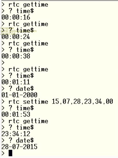
Smoke makes things work. When the smoke gets out, it stops! |
||||
| Geoffg Guru Joined: 06/06/2011 Location: AustraliaPosts: 3362 |
This sounds very much as if there is a fault with either the crystal or the battery on the RTC. I have had this problem in the past, what happens is that when you issue the RTC SETTIME command MMBasic sets both the internal MMBasic clock and the RTC. However, when you remove the power the RTC looses the time so it is reset to zero on the next power up. I can check the RTC code when I get back to my workshop but I doubt that MMBasic has a bug, the fault is probably in the RTC. Geoff Geoff Graham - http://geoffg.net |
||||
| Grogster Admin Group Joined: 31/12/2012 Location: New ZealandPosts: 9975 |
3231 has no crystal - it is inside the chip itself. Battery is brand new, and measures 3.07v. These are the cheap Chinese modules, and are probably rubbish anyway, so I will have a play with a genuine DS3232, which I also have some of. Smoke makes things work. When the smoke gets out, it stops! |
||||
| matherp Guru Joined: 11/12/2012 Location: United KingdomPosts: 11514 |
DS3231 module is working fine for me on MM+, also tested PCF8563 and DS1307 - all work properly. |
||||
| MMAndy Regular Member Joined: 16/07/2015 Location: United StatesPosts: 91 |
@Zonker You would think the "offshore" vendors would number the TFT SSD1963 LCD IDC 40 pin ribbon connector like you said but that is NOT the case. The display ribbon from the square pad (pin 1) is numbered 1-20 and restarts to 21 thru 40.  |
||||
| MMAndy Regular Member Joined: 16/07/2015 Location: United StatesPosts: 91 |
@WhiteWizzard & Grogster Thanks for the info on the MM+ E64 pin width "pitch" spacing of 0.9" or 22.86 mm. My board vendor would be very happy if I did the E 64 Bridge board several times. |
||||
| vegipete Guru Joined: 29/01/2013 Location: CanadaPosts: 1180 |
The PCBs and parts that Grogster sent me arrived fairly quickly and in good order. Trouble is, Microchip was estimating a 7 times longer lead time than Grogster's so all I can do for the next month is drool over the boards until the 470s arrive. Hopefully that doesn't cause any corrosion... Visit Vegipete's *Mite Library for cool programs. |
||||
| WhiteWizzard Guru Joined: 05/04/2013 Location: United KingdomPosts: 2991 |
Is there no kind-hearted (and local) TBS member that can send you a 470? |
||||
| bigmik Guru Joined: 20/06/2011 Location: AustraliaPosts: 2981 |
vP, You could always try digikey or one if RSComponents resellers. Regards, Mick Mick's uMite Stuff can be found >>> HERE (Kindly hosted by Dontronics) <<< |
||||
| Zonker Guru Joined: 18/08/2012 Location: United StatesPosts: 772 |
Yep... I got mine from Digikey and had them in 4 days... Also, I am once again a dumbass, as I was trying to get the 7" panel working on the "B20" release... Will get the "B23" release and try this again... Yikes...! |
||||
| The Back Shed's forum code is written, and hosted, in Australia. | © JAQ Software 2026 |
