
|
|
Forum Index : Microcontroller and PC projects : Keyboard for Micromite Plus
| Author | Message | ||||
| robert.rozee Guru Joined: 31/12/2012 Location: New ZealandPosts: 2541 |
nice PCB layout 
but one question: you talked earlier about the keyboard data being outputted to COM1, while on the board i can see only a console port. will you not need a second 3 or 4-pin header for COM1? if you did implement both TxD and RxD for COM1, as well as bring out the pins necessary for a TFT LCD to be attached (via SPI), then the keyboard + attached screen could be used as a miniature terminal at some future time. even if this was implemented as an MMbasic program, it would likely still be usable. cheers, rob :-) |
||||
Grogster Admin Group Joined: 31/12/2012 Location: New ZealandPosts: 9985 |
Yep, "Power" and "CAPS" LED's are on my PCB, and are designed to align with the keyboard top, so that those LED's will show through the top of the case like the original ones would have. "Power" is pulsed low with every keypress, so it blinks as you type, but if you are not typing, stays on as an "On" LED. "CAPS" LED is currently unassigned at this time. Old reset and on/off switch not used, and will be glued in place to stop them being pushed in. Smoke makes things work. When the smoke gets out, it stops! |
||||
| Grogster Admin Group Joined: 31/12/2012 Location: New ZealandPosts: 9985 |
Lack of pins. 
I elected to use the console as the output, but it also allows me to transfer the program to the chip, without actually removing the back of the keyboard. 
I will set the console to 19k2, or perhaps just leave it at 38k4. ...the latter is probably a good idea... TZA's nice scrunched matrix configuration allows for 8 x 9, so that is 17 pins, and we have 19. 17 + 2 I/O pins for the two LED's - we have a full ships' compliment of crew members. SPI out etc are also not available for the same reasons - I've used all the pins.Smoke makes things work. When the smoke gets out, it stops! |
||||
| robert.rozee Guru Joined: 31/12/2012 Location: New ZealandPosts: 2541 |
you could perhaps use a 74HCT154 4 to 16 decoder to drive the keyboard rows - this would free up 5 pins. and if the keyboard is scanned regularly, you could also transfer the two LEDs onto a couple of the spare decoded outputs if the LEDs were able to be operated at a reduced duty cycle, although the software side of driving the LEDs would then become a little more complicated. just speculative ideas, mind you. cheers, rob :-) |
||||
| Grogster Admin Group Joined: 31/12/2012 Location: New ZealandPosts: 9985 |
See TZA for your keyboard requirements in that respect.  Smoke makes things work. When the smoke gets out, it stops! |
||||
| MicroBlocks Guru Joined: 12/05/2012 Location: ThailandPosts: 2209 |
Ok here is my progress so far. I made it into a small module that can be added to any mcu. I left out all the connectors and power supply stuff as that is often already available. The pcb is 23x18mm. No software yet as i am waiting for the DIP parts to arrive. Schematic: 2015-08-24_202441_BBM_X2S.pdf pcb: 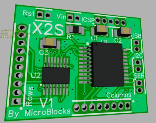
The BBM in the filename stands for something that i am working on for some time now. Still have a few problems to solve before i can announce it. :) Microblocks. Build with logic. |
||||
TassyJim Guru Joined: 07/08/2011 Location: AustraliaPosts: 6543 |
A question re the use of the 4017. Don't you need diodes to prevent shorting two of the outputs when two keys are pressed? Jim VK7JH MMedit |
||||
| MicroBlocks Guru Joined: 12/05/2012 Location: ThailandPosts: 2209 |
Jim, Good catch! I had them in my schematic before, but decided to take them out. They limit the possibilities. This module can be used for different purposes also. Like an Led matrix. Or a mix of switches and leds. Or maybe just as single outputs. Having the diodes mounted would limit its use, so i opted for having those on the pcb where this module will be put on. I also considered using a 1-16 analog multiplexer. Then only one output is active and all the others are in high impedance. This would need 4 pins of the PIC. There are also 1-8 multiplexers that need 3 bits but then i am one row short.Using those would not need diodes. I not rule out the 1-16 if more keys are needed. With this PIC i not have enough pins unless i sacrifice either I2C/Serial or USB. I also could use a 4 bit binary counter and connect the outputs to the input of a 1-16 multiplexer. That would also require only 2 pins from the pic. Hmm.... a 16x8 matrix. I will have to think about that a bit. I'll get some chips and test that too. :) Microblocks. Build with logic. |
||||
| Chris Roper Senior Member Joined: 19/05/2015 Location: South AfricaPosts: 280 |
Well you do have one more pin if you use #config MCLRE_OFF, then MCLR is available as RA3. Cheers Chris http://caroper.blogspot.com/ |
||||
| Grogster Admin Group Joined: 31/12/2012 Location: New ZealandPosts: 9985 |
My two black ones have arrived, and they have a slightly different PCB in them, and the matrix seems to be from a different supplier, but the matrix does appear to still be exactly the same - phew! 
These black ones have a green PCB which is slightly different in layout and fractionally larger then the blue PCB of the original one, and the matrix FPC is labelled as LONRU LR-105 K191-2. I have tried a couple of keys at random with the LED tester and TZA's neat matrix chart, and the LED lights exactly as expected for the random test keys, so I think the matrix is still common across all models. Personally, I can't see them using a different matrix between colours, but when things are made down to the last cent, there could be differences if one supplier could offer a cheaper matrix by a few cents - you all know the drill with mass production in the Chinese market. Smoke makes things work. When the smoke gets out, it stops! |
||||
OA47 Guru Joined: 11/04/2012 Location: AustraliaPosts: 1050 |
Today whilst doing the grocery shopping at one of the large stores starting with W, they had mini blue-tooth keyboards at around $12-13. Would these be similar to the ones being discussed ? GM |
||||
BobD Guru Joined: 07/12/2011 Location: AustraliaPosts: 935 |
Graeme which Woolworths in VIC would that be? Bob |
||||
bigmik Guru Joined: 20/06/2011 Location: AustraliaPosts: 2981 |
Hi Grogs, TZ, All, Not wishing to dampen anyones enthusiasm but I have to ask!! .. Why not use it as a bluetooth keyboard with the appropriate adapter/dongle on the uMite? Regards, Mick Mick's uMite Stuff can be found >>> HERE (Kindly hosted by Dontronics) <<< |
||||
| OA47 Guru Joined: 11/04/2012 Location: AustraliaPosts: 1050 |
The one on the south side of Bendigo. 
GM |
||||
| Grogster Admin Group Joined: 31/12/2012 Location: New ZealandPosts: 9985 |
@ Mick - that would require the MM or MM+ to support a USB keyboard natively, which they do not. There is talk about the MM+ going to support USB keyboards at some stage, but not sure when that is - it could be months or a year or more away(it's not as easy as supporting PS/2). I might ask Geoff for a more solid answer on if/when he is likely to implement this. The idea was also so that, as a serial keyboard, it could be used with just about anything that could use serial input - Arduino, PICAXE, MEGA, Raspberry Pi - so long as there is a spare serial port available, and there is no need to support any other protocol then. This is not a project for everybody, and you qualify your remarks
If the MM+ moves to supporting USB KB, then I will move to that protocol at that time. Smoke makes things work. When the smoke gets out, it stops! |
||||
| bigmik Guru Joined: 20/06/2011 Location: AustraliaPosts: 2981 |
Hi Grogs, Are there not serial to BT dongles like some wifi ones I remember seeing somewhere? Mick Mick's uMite Stuff can be found >>> HERE (Kindly hosted by Dontronics) <<< |
||||
| Grogster Admin Group Joined: 31/12/2012 Location: New ZealandPosts: 9985 |
Yeah, I looked for something like that, but they are all seem to be serial-over-bluetooth links, in that you can use them as a wireless serial link, using the bluetooth protocol. I was unable to find one that would pair-up with a bluetooth keyboard, and then output serial or some other form of useable data as sent by the keyboard. Perhaps I did not look hard enough, but all the serial bluetooth modules I could find, were just serial-over-bluetooth modules. Smoke makes things work. When the smoke gets out, it stops! |
||||
| bigmik Guru Joined: 20/06/2011 Location: AustraliaPosts: 2981 |
Hi Grogs, Is there something special in the kb that would stop These Modules from pairing with a keyboard? For the $3.xx I might buy one and play a bit. Regards, Mick Mick's uMite Stuff can be found >>> HERE (Kindly hosted by Dontronics) <<< |
||||
| BobD Guru Joined: 07/12/2011 Location: AustraliaPosts: 935 |
Mick Those modules don't seem to do BT profiles . They just seem to talk to each other and that's all. Bob |
||||
| Grogster Admin Group Joined: 31/12/2012 Location: New ZealandPosts: 9985 |
Agreed. These are actually the exact modules I was talking about. These, and other ones just like these ones. They form a wireless serial link from one module to the other, using the bluetooth protocol, but it is just a serial link, that uses the bluetooth protocol, and will totally ignore any bluetooth HID that tries to pair with it. To use a bluetooth KB like the ones I am playing with, you'd need a module that can pair with the KB, AS A KB, then interpret the codes coming from the KB(as USB) and convert them to serial to be of any use - not easy.
Hence the matrix hacking going on. Work out the matrix, then roll your own MM or other controller circuit as TZA and I are doing. Smoke makes things work. When the smoke gets out, it stops! |
||||
| The Back Shed's forum code is written, and hosted, in Australia. | © JAQ Software 2026 |
