
|
|
Forum Index : Microcontroller and PC projects : MicroMite+ Explore64 PCB 1C...
| Author | Message | ||||
| robert.rozee Guru Joined: 31/12/2012 Location: New ZealandPosts: 2527 |
i'm rather a fan of the above-bar approach, though the symbols '�' and '~' are also used to indicate inversion in propositional logic. i've seen the '-' sign sometimes used in texts when an above-bar is not available, though mathematically it is, strictly speaking, incorrect. sometimes a lower-case 'n' is also used: nMCLR, which seems like a tidy compromise ('n' for NOT). would a thin above-bar be possible to add? is it necessary, as most people do understand that MCLR is active low? if an above-bar is not possible and some sort of symbol really is required, my vote would be for '�' or 'n'. you my find the through-hole crystal is far easier to source cheaply, though there would be little harm in adding the pads to accommodate either footprint. in the past i've found SMD crystals a right pain to solder in place nicely, and almost impossible to reposition or remove intact. addendum: just had a look at the layout - an SMD crystal would likely only be easily located on the underside of the board, unless it was in a much smaller package. this would create production line assembly 'issues' far greater than any gains. cheers, rob :-) |
||||
| MicroBlocks Guru Joined: 12/05/2012 Location: ThailandPosts: 2209 |
The reason for using a # (or other character) was that in schematics the line above the word disappears because net lines go over it, same possibility on a pcb. On a pcb the silkscreen letters are often small, a ~ or - often end up very tiny or thin. A big fat # will at least have about the same size as the other letters. I like the suggestion of a 'n'. Seems a good compromise. An SMD crystal does often have a lower load capacitance. Typical it is 8uF for smd and 16pf for through hole components. Same for tolerances an SMD is about 20ppm, through hole 30ppm. ESR (lower is better) is too much depended on manufacturer but they often seems around the same. Power drive (lower is better) levels, again an SMD is about 50uW and through hole 100uW. Seems that smd crystals are often more expensive but also better suited for the task. A lower load capacitance is preferred as is stated in the datasheet of most mcu's from microchip. The capacitors used here are 22pf, those values are often for lower Mhz, for 20Mhz probably around 14pf would be a better fit but it all depends on what the datasheet of the crystals manufacturer says. The 20Mhz crystal is for me new territory, so i tend to read a lot about new things, and the above is stated many times in datasheets. The ones i used often and have experience with are 8Mhz and 12Mhz crystals and for those 22pf works pretty well. You don't want a risk of your crystal not starting or the signal starts clipping. Very random errors will then occur. This all might be a bit much, getting closer to a perfect match of parts is what it is about. The current design is more than good enough, so take all of the above as a compressed form of information only. Microblocks. Build with logic. |
||||
| vegipete Guru Joined: 29/01/2013 Location: CanadaPosts: 1177 |
Here is the plug I use for programming: 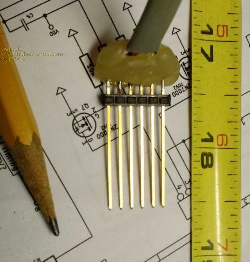
The long pins (tape measure is inches) are key to providing springiness so that light sideways pressure lets each pin make good contact. Note also 6 pins! Yes, one of the PICKit pins is not connected, but I prefer all 6 pins because it reduces the chance for error. Also, the choice of USB jack is evil. (That's just my opinion. ;-) It is not super easy to hand solder because the pins are part way underneath. Solder it on first, then check for shorts, before soldering other components. Visit Vegipete's *Mite Library for cool programs. |
||||
| atmega8 Guru Joined: 19/11/2013 Location: GermanyPosts: 738 |
Grog, ( Grog is a famous hot Drink here in Europe, Rum, tea, Sugar, Lemon...) Is a schematic available? THX |
||||
Grogster Admin Group Joined: 31/12/2012 Location: New ZealandPosts: 9975 |
@ vegipete - The 1C board here uses a more standard USB socket. The 1B's had the wee short USB socket, and yes - the pins on it were tricky to get to. Not so much an issue with the bigger more standard USB socket used on the 1C version of the board. @ atmega8 - The schematic is in the constructors pack, on the 1B thread, or available for download from here. The 1C schematic is slightly different around the 120/130 supervisory chip, but I will ask Geoff if he wants to prepare a new schematic, or I can rustle one up. Smoke makes things work. When the smoke gets out, it stops! |
||||
| MicroBlocks Guru Joined: 12/05/2012 Location: ThailandPosts: 2209 |
Would it be easy to renumber the parts. Normally you can reassign numbers to parts in your PCB design and back annotate them to your schematics. In Diptrace that i use it is called 'Refdes renumbering'. Then when reading a schematic and seeing the part number it would be easy to find on the pcb. Microblocks. Build with logic. |
||||
| Grogster Admin Group Joined: 31/12/2012 Location: New ZealandPosts: 9975 |
Geoff has said he will make a new schematic, and he will probably put the component references on the new schematic - that is a good idea.  Smoke makes things work. When the smoke gets out, it stops! |
||||
| atmega8 Guru Joined: 19/11/2013 Location: GermanyPosts: 738 |
Grogster, there Iss only the Hex File in the Download Link. |
||||
| Grogster Admin Group Joined: 31/12/2012 Location: New ZealandPosts: 9975 |
You are right - sorry - I need to fix that download, as it is missing some files. 
Here is a link to the V2 schematic that Geoff drew. This is how the current board sits - it is NOT the schematic for the 1C - that is coming soon. Smoke makes things work. When the smoke gets out, it stops! |
||||
| MMAndy Regular Member Joined: 16/07/2015 Location: United StatesPosts: 91 |
Grogs just curious ... Is the external 120/130 reset supervisor on the version 1c optional or permanent? Do you have to disable the "internal" reset setting(s) before using this IC? If so, how would you handle the different firmware settings? BTW ... from our battery pack testing, this reset supervisor is definitely needed. |
||||
| MicroBlocks Guru Joined: 12/05/2012 Location: ThailandPosts: 2209 |
The three choices are: 1 ) Mount a MCP130 supervisory chip. Not mount the pullup resistor. 2 ) Mount a MCP120 supervisory chip. Also mount a pull up resistor. 3 ) Mount a pull up resistor. The reset function is a fixed function of the MCLR pin. There is nothing that can enable/disable it in software. Microblocks. Build with logic. |
||||
| Grogster Admin Group Joined: 31/12/2012 Location: New ZealandPosts: 9975 |
Everything that TZA just said, but just to follow up on your specific question: NO - MCP120+resistor or MCP130 without resistor is OPTIONAL - note the arrow and word 'Optional' pointing to the MCP IC on the bottom silkscreen...... For 50 cents, I think it is good insurance, and any kits or modules I supply, will have this chip. However, if you DON'T want to use it, just don't install it, but in that case, you DO still need to install 10k resistor R1. Smoke makes things work. When the smoke gets out, it stops! |
||||
| The Back Shed's forum code is written, and hosted, in Australia. | © JAQ Software 2026 |
