
|
|
Forum Index : Microcontroller and PC projects : MM+, Explore 64 and Explore 100
| Author | Message | ||||
Grogster Admin Group Joined: 31/12/2012 Location: New ZealandPosts: 10005 |
Here is a PDF of the E100 pin-assignments: 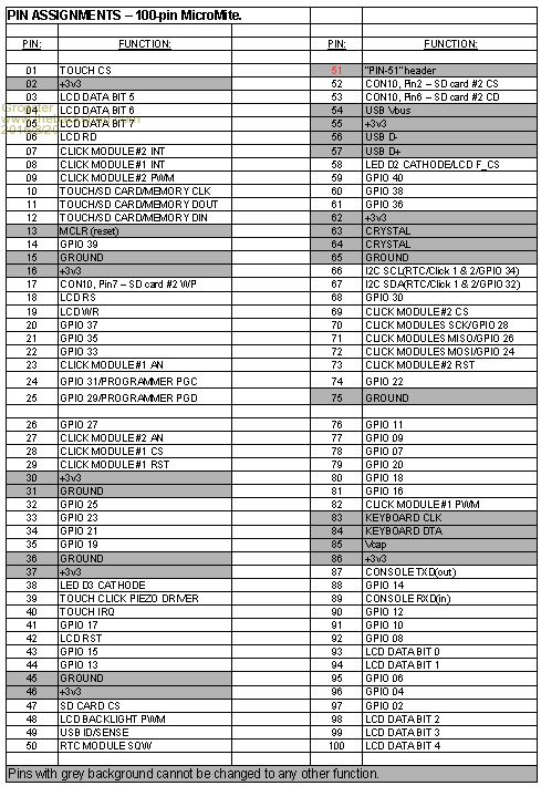
PDF: E100 Pin-Assignments, PCB Version 1B (August 2016) This might help those who are playing with the E100 before it is even published in SC magazine.  Smoke makes things work. When the smoke gets out, it stops! |
||||
| Phil23 Guru Joined: 27/03/2016 Location: AustraliaPosts: 1667 |
Here's one of Con8. Please double check before using it. Might try & add pin functions later. Phil. 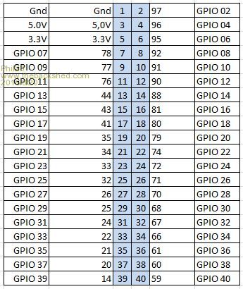
Edit:- Another with some descriptions. 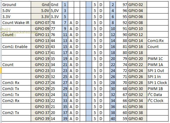
|
||||
| WhiteWizzard Guru Joined: 05/04/2013 Location: United KingdomPosts: 2991 |
Thats how far I got. I just wondered if there were a line or two of code to test the 'click'. GUI TEST TOUCH does nothing with a Piezo marked with polarity, so need something to get a 'response'
WW |
||||
| Phil23 Guru Joined: 27/03/2016 Location: AustraliaPosts: 1667 |
You should be able to test the click function with this. [Code]GUI Switch 1, "Test", 0,0,200,200, RGB(Cyan),RGB(Gray)[/code] If I do that I get the click responses. Just by executing that line at the prompt; don't even need to issue a RUN. Phil |
||||
mikeb Senior Member Joined: 10/04/2016 Location: AustraliaPosts: 180 |
@Grogster You nearly got the pinout right (CON10) 
Has Card Detect AND an activity LED. (Neat way of connecting the LED too). Schematic available on website. SD card breakout board (with CD) There are 10 kinds of people in the world. Those that understand binary and those that don't. |
||||
| Grogster Admin Group Joined: 31/12/2012 Location: New ZealandPosts: 10005 |
Hi Mike. 
Pin-53 is SD #2 CD ONLY: 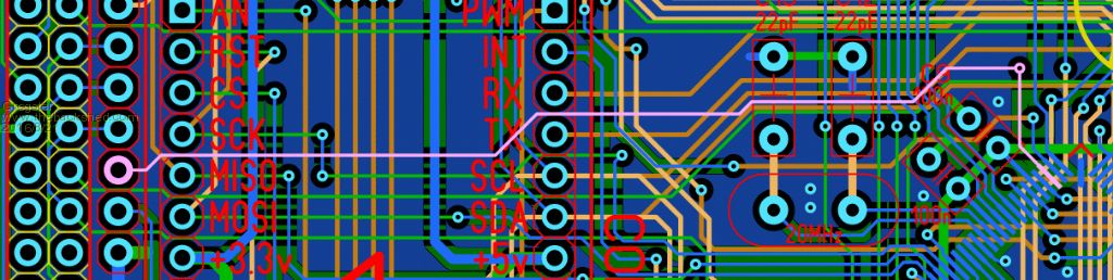
You are probably thinking of Pin-58, which is F_CS and LED D2 cathode - D2 will light whenever F_CS is pulled low. If there is an SPI flash memory chip fitted to the footprint on the LCD module, D2 will blink whenever you access this memory chip. In hindsight, it would have been a nice idea to have SD card activity LED's. This may well be something to add for a 1C version of the board. Smoke makes things work. When the smoke gets out, it stops! |
||||
| mikeb Senior Member Joined: 10/04/2016 Location: AustraliaPosts: 180 |
@Grogster I was referring to the LED on the breakout board. Sorry to be unclear. Re-reading my post I can see how you made the assumption of reference to your board. I remember a thread, recently, where a user wanted to see card activity. 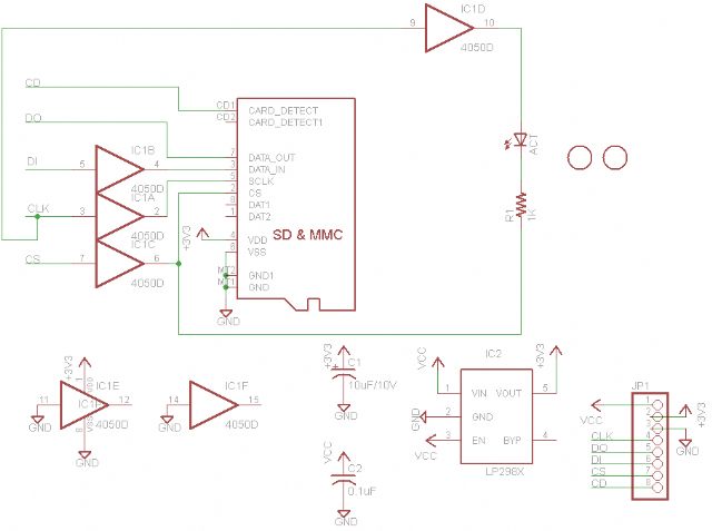
There are 10 kinds of people in the world. Those that understand binary and those that don't. |
||||
| Grogster Admin Group Joined: 31/12/2012 Location: New ZealandPosts: 10005 |
OH, I SEE!!!!! Whoops...... 
Yes, I thought you were referring to an error on CON10 - which could have been the case, but I could not find one, so I put up the image showing the trace. Ignore me.  Smoke makes things work. When the smoke gets out, it stops! |
||||
| mikeb Senior Member Joined: 10/04/2016 Location: AustraliaPosts: 180 |
@Grogster Nah.....Your board is all good. Sorry you wasted your time. I finally came across a 'breakout' board that actually included the 'card detect' signal (I think it is a critical signal just quietly). Funnily enough it had an 8 pin header on board but the pinout didn't line up with CON10. Just taking the p!5s. 
Maybe Ver 1C could include a connector for this board. Although, from what I've seen on the forum so far, many users will 'freak out' at the price. Me personally I'm a big believer in that 'You get what you pay for'. I'm always amused when people say they got something, on eBay, for next to nothing (with free shipping) and are then 'putout' cos it turns out to be dodgy.  There are 10 kinds of people in the world. Those that understand binary and those that don't. |
||||
| isochronic Guru Joined: 21/01/2012 Location: AustraliaPosts: 689 |
Are there any specific connections needed for the 470 software to run, apart from the usb and crystal? The reason I am asking, I have a generic board running with the 100 pin '470 chip ok, it would be a nice experiment to check the board wiring USB is ok with the 470 as well as the '795 |
||||
palcal Guru Joined: 12/10/2011 Location: AustraliaPosts: 2039 |
This may have already been discussed in this long thread but I am having trouble understanding the operation of the backlight on the SSD1963 TFT. The manual says it is PWM controlled but on the E64 and E100 pins 12 and 48 respectively are used which are analogue/digital pins. So what is the best place to put the jumper on the display. If I leave it on LED A do I use PWM and if I move it to 1963-PWM I use any digital pin. Paul "It is better to be ignorant and ask a stupid question than to be plain Stupid and not ask at all" |
||||
| Phil23 Guru Joined: 27/03/2016 Location: AustraliaPosts: 1667 |
For the E100, if the Display is in standard config; jumper on Led-A. Pin 48 would need to be connected to the Led-A pin on the display & then included in the options. Once the jumper is moved on the display, the connection to pin 48 is nolonger required & the option is set without specifying pin 48. Presume brightness is then controlled by commands on the data bus. I've had the E64 configured both way before I changed the display link. The SSD method provided much smoother control. Cheers. |
||||
| WhiteWizzard Guru Joined: 05/04/2013 Location: United KingdomPosts: 2991 |
@palcal, Personally I would set the TFT jumper onto 1963_PWM and then configure the OPTION LCDPANEL without the pin number (as the SSD chip will do it all). As Phil23 states, the Backlight brightness level is then VERY smooth for different BACKLIGHT settings. WW |
||||
| palcal Guru Joined: 12/10/2011 Location: AustraliaPosts: 2039 |
What is confusing is that the manual says to use PWM but even in standard config. PWM is not being used, Pin 48 is not PWM. Paul. Edit. Maybe it just clicked, in standard form I could use PWM but if I use The BACKLIGHT command it is not necessary ?? "It is better to be ignorant and ask a stupid question than to be plain Stupid and not ask at all" |
||||
Bryan1 Guru Joined: 22/02/2006 Location: AustraliaPosts: 2179 |
G'day Guy's, Well it has been awhile since I played with the explore64 and the last I used it was on my old computer that crashed so downloaded mplab for the IPE on my new computer and after several attempts got 5.2 programmed. So rebooted the computer and plugged in the usb only to find winsucks7 can't find the device driver for the recognized micromite plus. Had a look over Geoff's site but nothing there so now I'm wondering where to find this driver. Cheers Bryan |
||||
TassyJim Guru Joined: 07/08/2011 Location: AustraliaPosts: 6553 |
It's on the colour maximite download page. http://geoffg.net/Downloads/Maximite/Silicon_Chip_USB_Serial_Port_Driver.zip Jim VK7JH MMedit |
||||
| lew247 Guru Joined: 23/12/2015 Location: United KingdomPosts: 1709 |
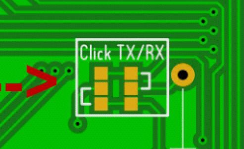
Quick question as I skimmed through this thread and couldn't see the answer Can anyone tell me what the 6 pcb squares marked click TX/RX means and how to use these? I presume they are solder points for jumpers for something? |
||||
| palcal Guru Joined: 12/10/2011 Location: AustraliaPosts: 2039 |
Have a look at page 1 of this thread and click on click boards. Paul. "It is better to be ignorant and ask a stupid question than to be plain Stupid and not ask at all" |
||||
| lew247 Guru Joined: 23/12/2015 Location: United KingdomPosts: 1709 |
 Thanks Palcal, I know what the click boards are, it's the 6 solder "squares" on the Explore 100, what they are for and how to use them I would like info about |
||||
| Phil23 Guru Joined: 27/03/2016 Location: AustraliaPosts: 1667 |
Geoff mentions these in October's Silicon Chip. They allow you to reverse the TX & RX pins on the Click board sockets. Both sockets use Com3, pins 25 & 26. The brackets show which pads to bridge to have them in the normal configuration. Cheers. Edit:- I overlooked them when I built my E100's, so I guess they won't work yet. I also found some 3x7cm proto boards on eBay that are ideal for connecting a few components to the sockets. |
||||
| The Back Shed's forum code is written, and hosted, in Australia. | © JAQ Software 2026 |
