
|
|
Forum Index : Microcontroller and PC projects : Armmite - STM32H7: Developments
| Author | Message | ||||
| cdeagle Senior Member Joined: 22/06/2014 Location: United StatesPosts: 269 |
Nice and clean Peter. Pins are easy to read, especially for a greybeard like me. |
||||
| TrevorH Senior Member Joined: 06/04/2018 Location: United KingdomPosts: 145 |
Hi again, Silly me thinking it was going to be simple. I am more or less OK with PIC IO but Arm is a whole new ballgame. Slowing it down certainly has a marked effect, but I don't understand why the colour makes any difference (It couldn't be the 565 conversion screwing up or something silly like that?). I am guessing. The PCB looking good so far (I never get on with these autorouting programs) I use Corel's Paint shop Pro for mine. I have found another problem for me anyway. Using the faster drivers, touch gives hardware failure, but using slower drivers calibrate locks up every time. Trevor. |
||||
| astro1 Regular Member Joined: 26/06/2016 Location: AustraliaPosts: 53 |
Daughter board ideas. Grouped connections for SPI, I2C & COM ports, power as well. This way it's easier to add other types of serial boards and SPI devices. For power maybe 2 rows of 10 pads, ground and 3v3. Or/and add extra 35x2 connector pads, top and bottom, labeled for ad-hock wire connections. Or all the other pins that aren't SPI, I2C or Com? A free pad area square for miscellaneous parts. Group by 2 pads with a route in between. Example: O-OO-O O-OO-O O-OO-O O-OO-O |
||||
| JohnS Guru Joined: 18/11/2011 Location: United KingdomPosts: 4332 |
Might it be partly to do with the rise time / drive strength? On quite a few chips you can change one or more of those. John |
||||
| TrevorH Senior Member Joined: 06/04/2018 Location: United KingdomPosts: 145 |
Hi peter, This corruption problem first arose for me when coupling these TFTs to PJRC's TEENSY boards from the Arduino camp. Paul Stoffregen built in the Teensy patch to the IDE, settings to change the speed of the processor. If you ran the M4 processor at full speed (180Mhz) problems arose with TFT, but if you used speeds below 120Mhz everything was OK. I was wondering IF this is the same problem, cranking the speed down when talking to the TFT could be the answer? I was also wondering if anyone else are having similar problems with their SSD1963 TFTs. Trevor. |
||||
| matherp Guru Joined: 11/12/2012 Location: United KingdomPosts: 11475 |
I've tried to incorporate the various suggestions for a daughter board. Here is the routed version and a view of the bottom showing the ground plane fill 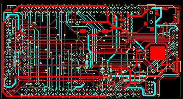 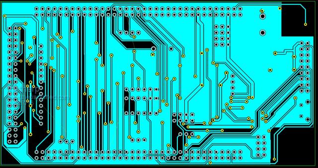 |
||||
| PCG68 Newbie Joined: 14/07/2018 Location: ItalyPosts: 16 |
Hi all, I'm new (in this forum, my first pc was a spectrum, so I'm not really new). Sorry for the language, I'm Italian and my English is bad. First of all thank you all for the interesting forum, but a special thanks to Peter and Geoff, I already have a maximite tft and micromite extreme, simply fantastic. Regarding the pcb I wanted to ask if you expected the fixing on the back of the tft (in this case dimensions and fixing holes). If then this display was a 7'' maybe there may be space for other connectors (nunchuck, mikroe etc ..) always that we can and that reflects the concept of this card. |
||||
| robert.rozee Guru Joined: 31/12/2012 Location: New ZealandPosts: 2527 |
it is because we are moving up into the realm of a bit of wire no longer acting like a bit of wire, but instead like an RF transmission line. see: https://en.wikipedia.org/wiki/Transmission_line there are NO simple/cheap solutions, beyond slowing things down. the complex/expensive solution is software that analyses each PCB trace and calculates either a target length (remember those squiggly little tracks on PC motherboards?), or a set of values for small series resistors (resistor values based on trace length, capacitance to adjacent copper, etc). it is all very much a black-art. cheers, rob :-) |
||||
| matherp Guru Joined: 11/12/2012 Location: United KingdomPosts: 11475 |
Trevor If you still have an LCD panel set up please could you test the various drivers with the attached and let me know the results Thanks 2018-07-16_222031_Armmite.zip This version also includes a new command WS2812 pinno, array_of_colours%() This sends the correct pulses to light WS2812 leds. The array should be of the exact length of the number of LEDs. The pin needs to be set as an output. So my test program for 7 LEDs is Option explicit option default NONE dim b%(6)=(rgb(red), rgb(green), rgb(blue), rgb(Yellow), rgb(cyan), rgb(magenta), rgb(white)) setpin 1,dout ws2812 1,b%() 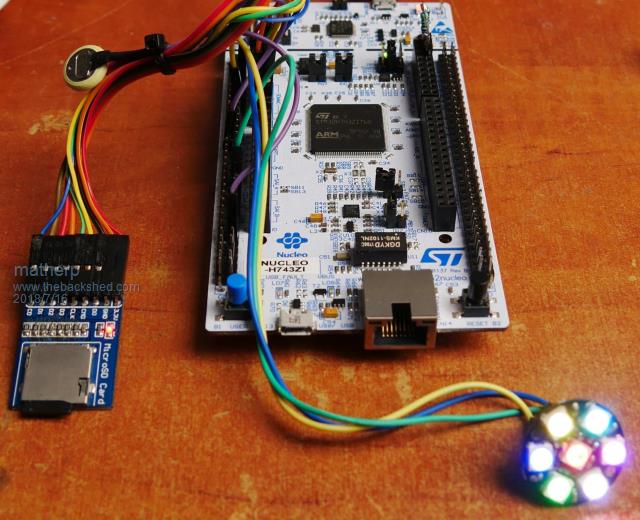 |
||||
| TrevorH Senior Member Joined: 06/04/2018 Location: United KingdomPosts: 145 |
Hi Peter, It's looking good from this end.  Results as follows:- These tests are using my previous test but this time in a do loop with "pause 500" before loop to prove reliability. What did you do?  ps. still can't get GUI CALIBRATE to work on TOUCH. A different problem I fear. Trevor. |
||||
| matherp Guru Joined: 11/12/2012 Location: United KingdomPosts: 11475 |
The HAL definition for the F7 has one 32-bit register for the GPIO BSRR. Setting a bit in the top 16 bits sets the output to 0. Setting a pin in the bottom 16 bits sets the output to 1. The H7 HAL has split this into two registers BSRRL and BSRRH and BSRR is no longer defined at all so making code conversion just a little harder Now you might think that setting BSRRL (L=low?) clears the output and BSRRH (H=high?) sets the output - that would make sense to me but no....... BSRRH means the high 16 bits which set the output to 0.  I'll post another update in a few mins that speeds up 8-bit as I hacked both versions to slow UPDATE 2018-07-17_034946_Armmite.zip |
||||
palcal Guru Joined: 12/10/2011 Location: AustraliaPosts: 2039 |
Where do I download 'STM32CubeProgrammer' I have tried downloading from 'www.st.com' but the activation email never comes. Paul. "It is better to be ignorant and ask a stupid question than to be plain Stupid and not ask at all" |
||||
| panky Guru Joined: 02/10/2012 Location: AustraliaPosts: 1127 |
Paul, I got my copy from here and they sent an activation email to the email I entered as part of the registration process. Doug. ... almost all of the Maximites, the MicromMites, the MM Extremes, the ArmMites, the PicoMite and loving it! |
||||
| palcal Guru Joined: 12/10/2011 Location: AustraliaPosts: 2039 |
I have tried that twice and the activation email never arrives. May be a problem, will try again later. Paul. edit. Ok got it sorted, didn't like the email address I used (Gmail) so used different address. Then the install needed Java which is not compatible with Firefox? so changed default browser to Edge and all OK. Update.. The board arrived while I was busy with that All working, now to connect a display. "It is better to be ignorant and ask a stupid question than to be plain Stupid and not ask at all" |
||||
| matherp Guru Joined: 11/12/2012 Location: United KingdomPosts: 11475 |
Check which pins you are using for T_CS and T_IRQ. Some of them are compromised by the Ethernet circuitry. I have removed SB178, SB181, sb165, sb156 and the JP6 and JP7 jumpers You should be able to see the T_IRQ line responding to touch with a multimeter |
||||
| TrevorH Senior Member Joined: 06/04/2018 Location: United KingdomPosts: 145 |
I have removed suggested links and retried calibrate. Calibrate screen comes up OK, first touch OK, second touch is followed by blank screen.  Edit:- IRQ is dropping on touch!! even after second touch. Trevor. |
||||
| matherp Guru Joined: 11/12/2012 Location: United KingdomPosts: 11475 |
Which pins are you using for T_IRQ and T_CS? Sorry can't do any testing at this end my board has died  |
||||
| TrevorH Senior Member Joined: 06/04/2018 Location: United KingdomPosts: 145 |
T_CS - processor pin 114 or PD00 T_IRQ - processor pin 115 0r PD01 Trevor. |
||||
| matherp Guru Joined: 11/12/2012 Location: United KingdomPosts: 11475 |
Check the SPI connections T_CLK= PF7 T_DO=PF8 (MISO) T_DIN=PF9 (MOSI) |
||||
| TrevorH Senior Member Joined: 06/04/2018 Location: United KingdomPosts: 145 |
Hi Peter, On page 2 of this thread you quoted:- I took this as TOUCH_IN as DIN and TOUCH_OUT as DOUT. Having swapped these round it now works BUT I get calibration error:- Warning: Inaccurate calibration Deviation X = 89, Y = 90 (pixels) It's not always the same numbers but when doing touch test, pen is way off the mark. Have I missed something else?? I always seem to get MISO and MOSI the wrong way round.  Trevor. |
||||
| The Back Shed's forum code is written, and hosted, in Australia. | © JAQ Software 2026 |
