
|
|
Forum Index : Microcontroller and PC projects : ArmmiteF4 firmware V5.07.00b1 - major upgrade
| Author | Message | ||||
| jaybek Newbie Joined: 25/05/2020 Location: GreenlandPosts: 18 |
Windows 10 Home Edition Version 20H2 STM32CubeProgrammer release v2.7.0 And the upload is without display connected. Jens #MeTo ZX81 |
||||
TassyJim Guru Joined: 07/08/2011 Location: AustraliaPosts: 6549 |
I went through my small collection of F407 boards. The ones with STM32F4VE and Ver: 2.1 on the back work as expected with one jumper required for flashing and all jumpers removed for normal use. I do have one board that has STM32F4XX and V2.0 on the back. It does definitely have a STM32F407VET6 processor. On that board, I have to have the two jumpers in place for flashing and the BT0 to ground jumper in place for normal use. In other words, that board does NOT have the pulldown resistors shown in the circuit diagram and mentioned in the manual. If you are having trouble getting the serial to work once flashed, try with a jumper from BT0 to GND I don't have any jumper on BT1 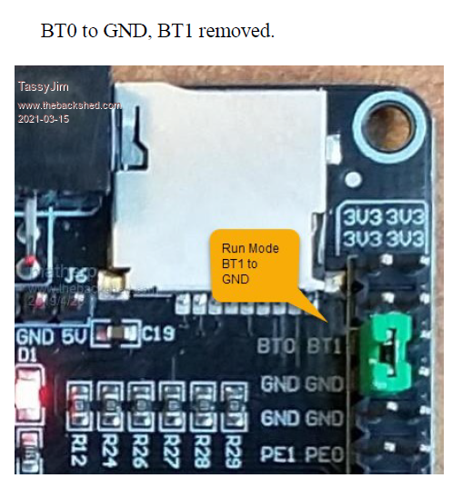 The text on the photo (taken from the manual) is incorrect. It should read BT0 to Ground Jim VK7JH MMedit |
||||
disco4now Guru Joined: 18/12/2014 Location: AustraliaPosts: 1133 |
Thanks Fixed next release.  F4 H7FotSF4xGT |
||||
| lizby Guru Joined: 17/05/2016 Location: United StatesPosts: 3825 |
There must be some variation. My V2.0 boards run with no jumpers at all (flash as per normal). PicoMite, Armmite F4, SensorKits, MMBasic Hardware, Games, etc. on FOTS |
||||
| TassyJim Guru Joined: 07/08/2011 Location: AustraliaPosts: 6549 |
I checked my V2.0 board and it does have R7 and R8. I will do some measurements when time permits. Perhaps the value is wrong or just marginal. Either way, the board I have definitely needs the grounding jumpers in place for correct operation. The boards I have were all purchased 18 months ago. I have more on order so it will be interesting to see what they perform like. Jim VK7JH MMedit |
||||
| RetroJoe Senior Member Joined: 06/08/2020 Location: CanadaPosts: 290 |
I'm still working on (hopefully) getting my F4 board to spring to life, and began to do some research on diagnostic tools and troubleshooting routines. More questions than answers at this point, so hoping maybe the F4 veterans here can answer some of them: 1) Is this board design known colloquially as the "Black Board"? I believe there is a "Blue Board" and a "Discovery Board" that also use the F4 chip, both of which are substantially more expensive than the Black Board. 2) My board is a Rev 2.3 - who notionally manages the reference design for this board e.g gets to decide what design changes occur in a particular revision? And, does the revision matter to Peter's Armmite firmware? 3) Are there any brands / manufacturers for these boards that are more reliable than others? I would hate to buy another one and have that be DOA as well. 4) To reduce the number of variables, I am religiously strapping the BT0 pin high for FW upload, and BT0 low for normal operation. Can I assume that BT1 can be left floating, and plays no possible role in my board not booting properly? 5) Finally, what is the role / purpose of the "ST Link" device? Closest I can figure, this would be the piece of kit I need to perform low-level diagnostics on the board HW. Enjoy Every Sandwich / Joe P. |
||||
| lizby Guru Joined: 17/05/2016 Location: United StatesPosts: 3825 |
This is not the "Black pill" version of the STM "Blue pill". Don't know about your Rev 2.3. All the ones I have (8) are at least 18 months old, and the three I've looked at are V2.0. I have no idea if newer ones break MMBasic, and I doubt anyone will know until there are more datapoints. After flashing with BT0 high and BT0 low, my boards work with no jumpers at all. EXCEPT: I have one which just quit powering up with a working usb (more later on a subsequent thread if I find out more) but I flashed it with the latest; got the MMBasic prompts and set the time, unplugged and plugged in my F4 hat which has a pi-type connector, powered up again and checked the time; powered down and plugged in my pi-connector sensor board, powered up and flashed some lights on it; and then powered down and up again with no USB. I've reflashed, but no usb. Swapped USB cables because I once had problems with one. And now, after dinner, just plugged it in again and have a usb com port. But the date is 01-01-2000, so maybe my battery is bad. I'll try replacing it. (Maybe with my earlier use today the more than 2-year old battery ran down, and after sitting for 2 hours partly recovered--could that have an effect on the USB port presenting?) PicoMite, Armmite F4, SensorKits, MMBasic Hardware, Games, etc. on FOTS |
||||
| TassyJim Guru Joined: 07/08/2011 Location: AustraliaPosts: 6549 |
This is the rear of my two versions. 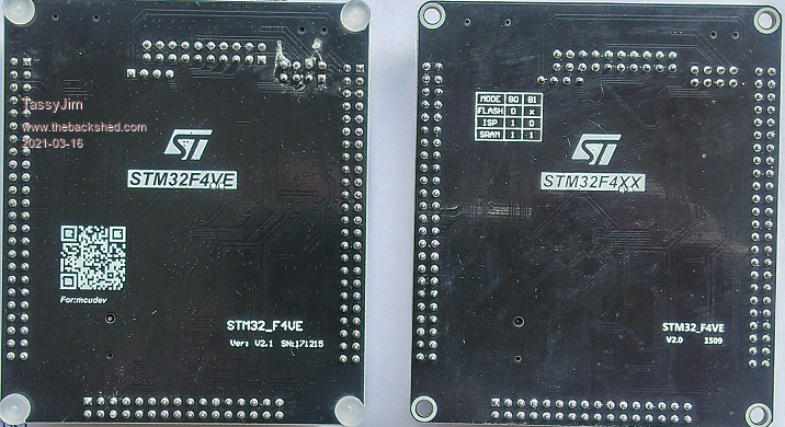 The V2 board one requires the jumpers in place for firmware programming and also normal running. I measured the resistors and that ARE in place and the correct values. Something makes the jumper to ground required on that board. Note that the jumper settings on the silk screen differ from the jumper settings in the circuit diagram supplied here. I believe that the circuit diagram supplied here is wrong. I have a Chinese version of the circuit: 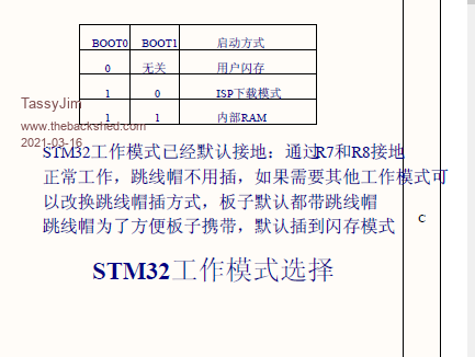 I have some more units on order. It will be interesting to see what revision board they use. If your V2.3 board doesn't work with the jumpers set as per the images in the manual, I don't know what else to suggest. Having the jumpers on will not cause any problems on the 'good' boards. While BT1 shouldn't need a jumper for normal running, I would try both positions. Jim VK7JH MMedit |
||||
| phil99 Guru Joined: 11/02/2018 Location: AustraliaPosts: 3324 |
Re SD Card issues. My board (STM32_F4VE Ver: V33 SN: 1911Z) reads some cards and not others. Even for cards it can read odd things happen. Eg the FILES command lists up to "Press any key to continue" then locks up, but only when OPTION LCDPANEL CONSOLE enabled. TassyJim's photo a few posts up shows 6 10k pullups connected to the SD card socket. R12, 24, 26, 27, 28, 29. My board doesn't have them, nor pads to fit them, relying on weak pullups in the chip. I think that could result in slow rise times and/or crosstalk between PCB tracks. I will order some SMD resistors an try fitting them directly to the SD socket pads. If anyone with SD problems and resistors on hand could also try it and let us know what happens. Pins 1, 2, 3, 5, 7, 8 use pullups. EDIT Salvaged an 8.2k X 8 SIL package from a dead motherboard and connected it to the SD socket and +3.3V and now all SD cards work error free. The schematic PDF for the board shows pullups all over the place that my board does not have. If any one has issues with any hardware compare your board to the schematic, it could save a lot of head scratching. Cost cutting gone too far I think. Edited 2021-03-16 17:01 by phil99 |
||||
| twofingers Guru Joined: 02/06/2014 Location: GermanyPosts: 1767 |
Thanks Phil, good to know. Same issues here (with V33) ... Kind regards Michael 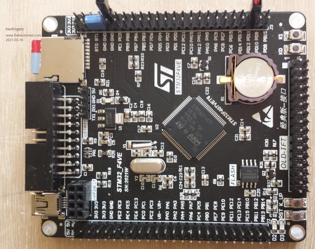 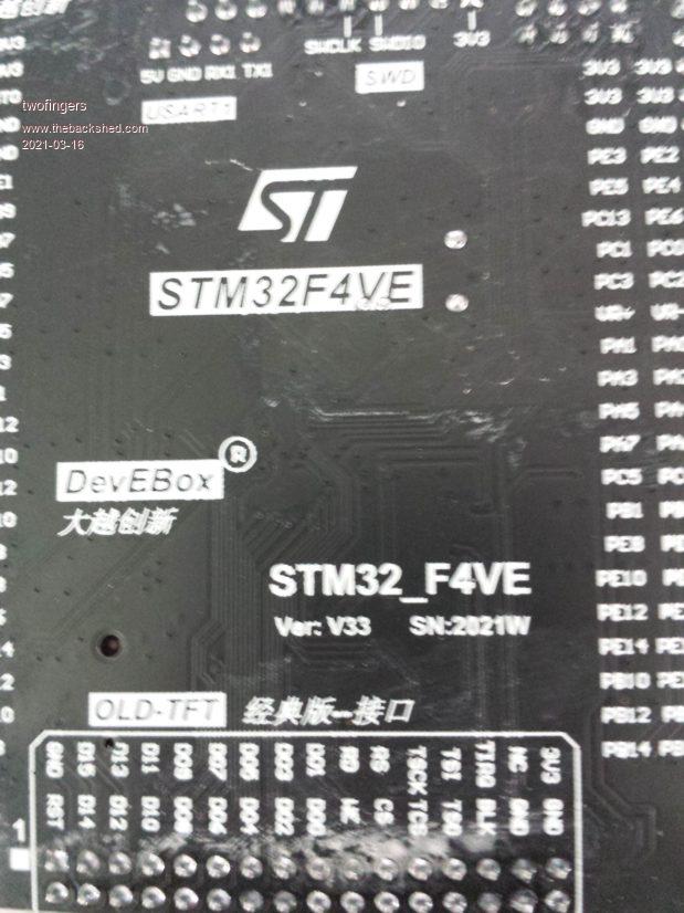 Edited 2021-03-16 20:41 by twofingers causality ≠ correlation ≠ coincidence |
||||
| matherp Guru Joined: 11/12/2012 Location: United KingdomPosts: 11661 |
The SSDcard must have pullups on the 4 data lines but not on the clock and doesn't matter on the CMD pin. The ST recommendation for pullups is 47K twofingers. Please could you try the attached on your board as-is and let me know if any different ArmmiteF407.zip |
||||
| Volhout Guru Joined: 05/03/2018 Location: NetherlandsPosts: 5998 |
Now I am getting curious what version I have...(and the one I had, the one that refused to enumerate on USB). Vxx V2.0 V2.1 V2.3 V33 Are there more ?? PicomiteVGA PETSCII ROBOTS |
||||
| twofingers Guru Joined: 02/06/2014 Location: GermanyPosts: 1767 |
Hi Peter, thanks for the quick response.  I think it (the new 5.07.00b7) makes not a big difference.  I tested 6 SD cards: Not working (Files: Error : SD Card not found) 1 GB FAT32 2 GB FAT32 (* was responding once, then: SD card not found) 8 GB FAT32 Working (at a first glance) 2 GB FAT 32 GB FAT32 (Sundisk Ultra) 32 GB exFAT (Samsung EVO) ======================================= BTW. A minor issue: Please take a look at the print function regarding tabs (i.e. commas). Print " 1 2 3 4 5 6 7" Print "1234567890123456789012345678901234567890123456789012345678901234567890" Print "0123456789",,,"0123456789" Print ,,,"0123456789" Output: 1 2 3 4 5 6 7 1234567890123456789012345678901234567890123456789012345678901234567890 0123456789 0123456789 0123456789 OPTION TAB does not work/has no function. Ah yes, many thanks for your amazing work on the Armmites.  Kind regards Michael Edited 2021-03-16 22:24 by twofingers causality ≠ correlation ≠ coincidence |
||||
| lizby Guru Joined: 17/05/2016 Location: United StatesPosts: 3825 |
When F4 failed yesterday after working earlier and having correct date ... Since I replaced the battery, the board has not failed to present its USB serial port. Replacing the battery is worth a try for those having trouble. (Does Peter know if there's a good explanation for why this might happen?) PicoMite, Armmite F4, SensorKits, MMBasic Hardware, Games, etc. on FOTS |
||||
| matherp Guru Joined: 11/12/2012 Location: United KingdomPosts: 11661 |
The firmware has to be able to start the RTC to work. However, the circuit has a dual diode connecting the battery and the 3.3V rail to the RTC power so it should work fine without a battery. If that diode is missing or faulty (they have installed a transistor instead!) then there will be an issue. I've got two boards - same versions as Jim - and they both work fine without batteries. They both have the SDcard pullups fitted and I don't see any issues with any SDcard I've tried. Typically I use a 32Gb Sandisk as they are now as cheap as anything smaller. |
||||
| phil99 Guru Joined: 11/02/2018 Location: AustraliaPosts: 3324 |
SD card update. As pullups should only be required on the 4 data pins I disconnected them from CMD and CLOCK. Reading SD cards became unreliable again. Reconnecting CMD fixed it. On my board I need pullups on pins 1,2,3,7,8 but not 5 (CLK). |
||||
| disco4now Guru Joined: 18/12/2014 Location: AustraliaPosts: 1133 |
I have two of the V33 boards with no pullups. I loaded this version into 1 and files command works on about the 5th go and then seems to keep working. Remove and replace the 16M SDCARD and it needs a few repeats of the command to get it going again. The other one with older software does not see SDCARD at all, so maybe its doing something? Are SDIO-1,2,3 used, if not could they have internal pullups so you would only need to add two resistors? F4 H7FotSF4xGT |
||||
| TassyJim Guru Joined: 07/08/2011 Location: AustraliaPosts: 6549 |
I couldn't find a circuit diagram for the V33 boards but I found this reference to another difference: We are only using the USB as a slave so may not be an issue but the lack of the D+ pullup should be noted. The V33 is a very different beast. Provided it is only a few pullups missing (and they have pins on the IO), it is not a show-stopper. Putting the pullups at the socket is the correct place but I would try the easy way out first and try the IO pins instead. Jim Edited 2021-03-17 16:55 by TassyJim VK7JH MMedit |
||||
| matherp Guru Joined: 11/12/2012 Location: United KingdomPosts: 11661 |
One more minor tweak for the SDcard. Please report impact (or not) ArmmiteF407.zip |
||||
| Bizzie Senior Member Joined: 06/07/2014 Location: AustraliaPosts: 192 |
Hi All, I took delivery of an F4 (STM32_F4VE) today Ver: V33 SN:2021W, loaded it with the bin above put a Transcend micro 2GB card in and files worked straight off. I do not have any other cards to try at this stage. A problem with the editor in colour mode though. See below 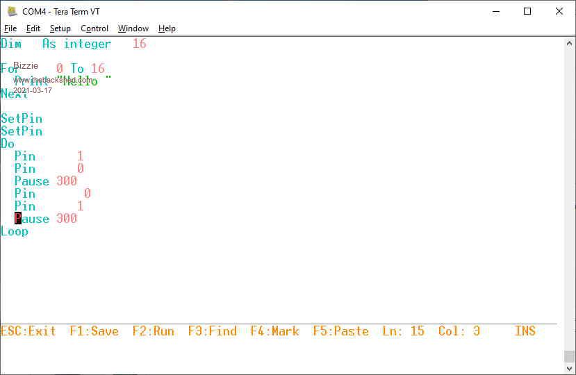 I am using Tera Term so assume all should be OK. Regards Rob White |
||||
| The Back Shed's forum code is written, and hosted, in Australia. | © JAQ Software 2026 |
