
|
|
Forum Index : Microcontroller and PC projects : Flash 3 common catode LED lamps.
| Author | Message | ||||
| Mixtel90 Guru Joined: 05/10/2019 Location: United KingdomPosts: 8911 |
I still like the VOM1271. Less components, less hassle with values for the bootstrap. If you are charging anything for assembly time then they probably work out cheaper than the cost of the other bits, particularly if you have a little pcb made to take the mosfets, driver components and terminals (and for a quantity of 200 3-channel switch modules - that's 600 mosfet drivers - that's a no-brainer). You get power supply isolation thrown in for free if you want it and no signal inversion necessary. Look - solid state has tempted me away from relays! (Although they are still cheaper). (No gusto was harmed in the making of this post) Edited 2021-08-05 21:12 by Mixtel90 Mick Zilog Inside! nascom.info for Nascom & Gemini Preliminary MMBasic docs & my PCB designs |
||||
| PeterB Guru Joined: 05/02/2015 Location: AustraliaPosts: 669 |
G'Day Mick. I'm with you but Bob seems keen on his particular configuration. I do not think I have ever harmed a gusto but since I have no idea what they look like I thought perhaps I should buy one. In Oz we have a word similar to manano but without manano's sense of urgency, perhaps that's got something to do with it. Peter  |
||||
| CaptainBoing Guru Joined: 07/09/2016 Location: United KingdomPosts: 2171 |
Mi Gusto is spanish for "I like it", also a brand of cheap-ish (like sub GBP10) cuban cigars... as with all havanas they are purported to be rolled on a dusky maidens thigh for added erm, thinginess... As you have already discovered,my purile pom humour is best quickly skipped over  |
||||
| Mixtel90 Guru Joined: 05/10/2019 Location: United KingdomPosts: 8911 |
@PeterB I think it might. :) My main worry would be Vbc for Q. The collector will be at 28v and the base at 5v, that's -23V. If the junction should break down that could be 28v onto the arduino pin, albeit current limited. A reverse-biased diode from the arduino pin to its supply might be a good idea (if there isn't one built in). Mick Zilog Inside! nascom.info for Nascom & Gemini Preliminary MMBasic docs & my PCB designs |
||||
| Tinine Guru Joined: 30/03/2016 Location: United KingdomPosts: 1646 |
  You and me both. I must've missed something really dumb or I would've grabbed a bunch of TLP350H's and the whole thing would be done and dusted. You and me both. I must've missed something really dumb or I would've grabbed a bunch of TLP350H's and the whole thing would be done and dusted.Edited 2021-08-06 02:38 by Tinine |
||||
| Mixtel90 Guru Joined: 05/10/2019 Location: United KingdomPosts: 8911 |
Just had a look at the data sheet. Interesting chip, but the output power dissipation is only 260mW. The output seems to drop about 2.5V (which seems high to me). If that's true then the *continuous* output current is only about 100mA, even though it can handle over 2A peak current. I couldn't see a continuous current rating anywhere on the data sheet. It's a nice driver but won't give the voltage to overcome Vgs in this case. It would be fun to try one but it might cook. :) Mick Zilog Inside! nascom.info for Nascom & Gemini Preliminary MMBasic docs & my PCB designs |
||||
| Tinine Guru Joined: 30/03/2016 Location: United KingdomPosts: 1646 |
@Mixtel90 Continous current had me scratching my head, also. I have a handful of these things, will see if I can grab the time to load them up, over the weekend. I have 2A, 24v solenoid valves which should be a good test  |
||||
| Solar Mike Guru Joined: 08/02/2015 Location: New ZealandPosts: 1214 |
Refer to Note 2 in the spec sheet, these are not suitable for driving a large current for a long duration. Cheers Mike |
||||
| bob.steel Senior Member Joined: 27/02/2020 Location: AustraliaPosts: 188 |
Didn't understand what you mean by this? |
||||
| Mixtel90 Guru Joined: 05/10/2019 Location: United KingdomPosts: 8911 |
The base of the transistor is held at 5v. It can't turn on unless the base is 0.6v higher than the emitter, so if the emitter is pulled down to GND by the arduino output the transistor will turn on. That will pull the mosfet gate low and turn it off. If the arduino output goes high the emitter will go up to 5v, like the base, so the transistor will turn off. The resistor will then pull the mosfet gate high and it will (in theory anyway!) turn on. Note that all current that passes through the mosfet pull-up resistor has to pass through the transistor and the arduino's output, so the resistor mustn't be too low or the arduino will fry. Mick Zilog Inside! nascom.info for Nascom & Gemini Preliminary MMBasic docs & my PCB designs |
||||
| bob.steel Senior Member Joined: 27/02/2020 Location: AustraliaPosts: 188 |
But which circuit is Peter talking about . The one I posted or CB's addition? And is the VOM1271 unsuitable because of its low current ability. ? I ordered 5 earlier on first mention to try anyway. I cant find any SSR 's for 5 volts drive with 30 volts DC output terminals. All ideas are being tried but I'm just waiting on parts coming in here and there so I have not settled on anything yet. And its 20 to build not 200 fortunately. A circuit board will be made and ordered when I do settle . Thanks all. Edited 2021-08-06 08:25 by bob.steel |
||||
| Tinine Guru Joined: 30/03/2016 Location: United KingdomPosts: 1646 |
Can't believe this thread...it must be some kind of test to see how much such nothingness can be overcomplicated or beat to death. 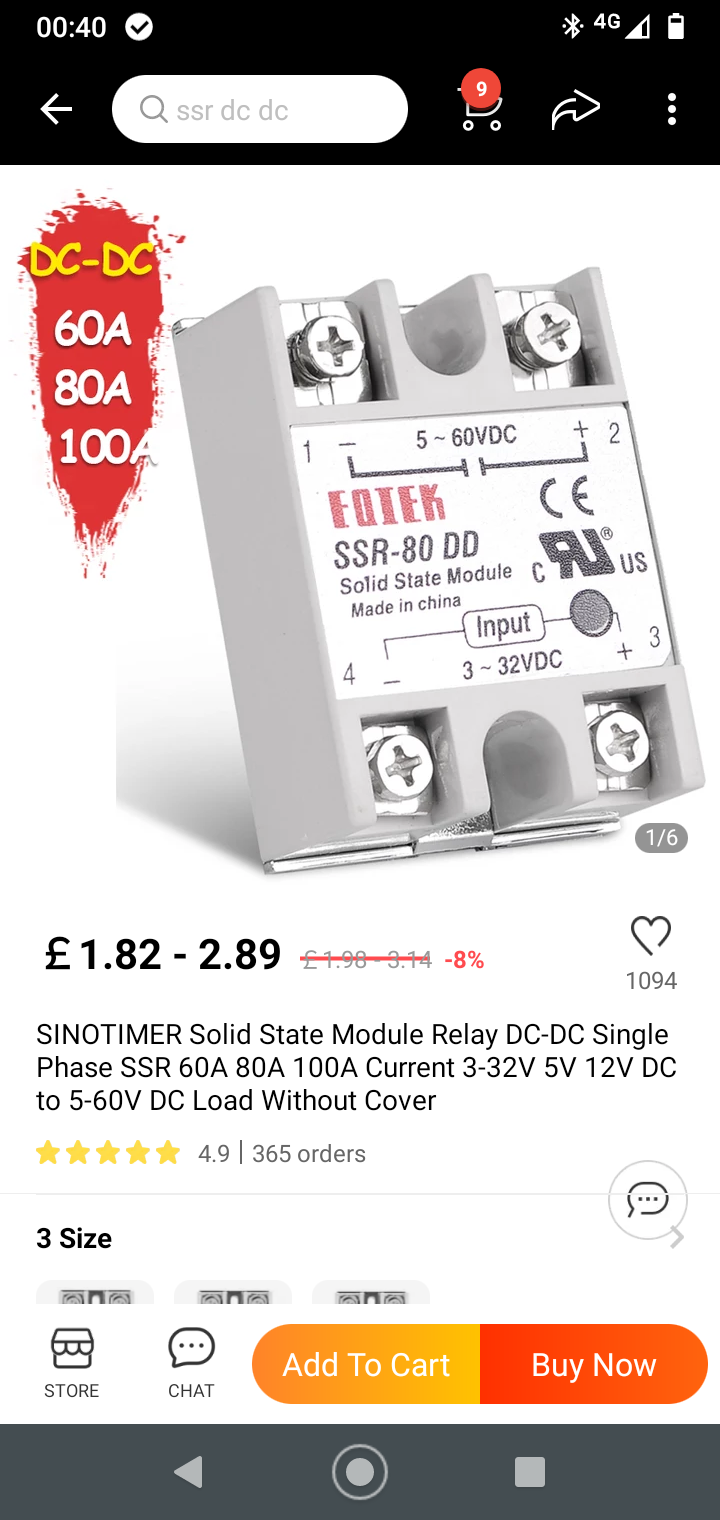 Edited 2021-08-06 10:09 by Tinine |
||||
| PeterB Guru Joined: 05/02/2015 Location: AustraliaPosts: 669 |
G'Day again Bob, I was talking about your circuit on page 5 showing DRIVE IN connected directly to an ARDUINO pin. Connecting an ARDUINO pin directly to the base of a transistor would result in death and destruction. If you need further clarification ( after Mick's explanation )of my modification let me know. Tinine, correct me if I'm wrong but the TLP350H is a simple opto isolator similar to the 4N25 etc and, as such, will not produce the +ve voltage required by Bob's P chan. FETS. The VOM1271 is very clever in that it does generate a +ve voltage. DC solid state relays have been around for years but in the past they have been expensive but they are a possible for Bob's system but he wants to use his P chan. FETs. If the lights went out in London it means CB tried my circuit and it failed. OOOOOPS. |
||||
| Tinine Guru Joined: 30/03/2016 Location: United KingdomPosts: 1646 |
@Mixtel90 and I are a bit befuddled by the lack of a continuous current rating but the peak is claimed to be up to 2.5A All I have found is references to this device being PWM driven. Wouldn't this mean that every pulse would be peak current? I dunno but I have a handful of these devices to test over the weekend. Am I being over-optimistic/naive in expecting these devices to be able to drive Bob's load directly? If my video shows a bunch of white smoke...we'll know |
||||
| Tinine Guru Joined: 30/03/2016 Location: United KingdomPosts: 1646 |
TLP350H 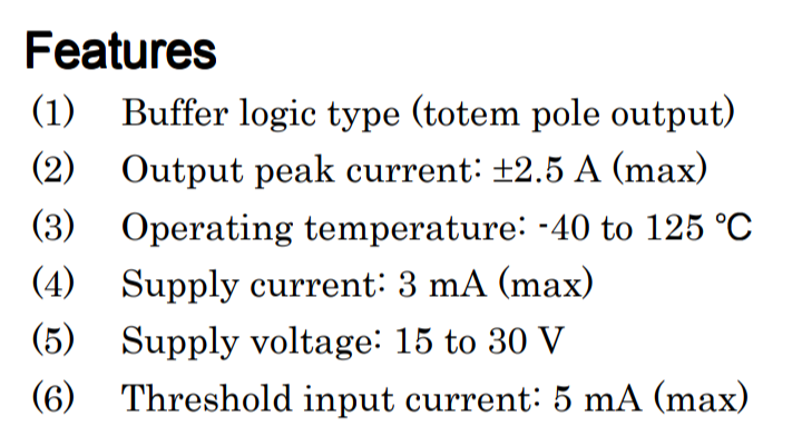 |
||||
| PeterB Guru Joined: 05/02/2015 Location: AustraliaPosts: 669 |
OOPS Sorry Tinine, Bob is using a IRF540 N channel FET as a source follower because his load is connected to ground and hence the gate needs to be taken well above 28V. I hope I've got it right this time. Can we go back to transistors .......please. Peter |
||||
| Turbo46 Guru Joined: 24/12/2017 Location: AustraliaPosts: 1693 |
Check out the conditions for the 2.5A (note 2) Note 2: Exponential waveform. Pulse width < 0.3 us, f < 15 kHz If I'm not badly mistaken, both the TLP350H and VOM1271 are drivers not load switching devices. The VOM1271 may be able to drive Bob's MOSFETs but not drive the load directly. Beware, if you let the magic smoke out it won't go back in. Bill Keep safe. Live long and prosper. |
||||
| Solar Mike Guru Joined: 08/02/2015 Location: New ZealandPosts: 1214 |
TLP350: those ratings are specified for driving a capacitive load with a very short duration, not for constant load. Its all in the spec sheet. Note 2: Exponential waveform pulse width PW < 0.3uS, f < 15 kHz Expected current pulse duration less than 300 nS They will blow up running the led lights directly. Cheers Mike |
||||
| PeterB Guru Joined: 05/02/2015 Location: AustraliaPosts: 669 |
FETs are often thought to be the ultimate solid state switch. They are not. The big problem is the very large gate capacitance that has to be charged and discharged quickly and at the sort of frequencies these things run at, that can be a problem and leads to devices like the TLP350H which is designed to deal with that capacitance. Peter |
||||
| phil99 Guru Joined: 11/02/2018 Location: AustraliaPosts: 3293 |
" Its all in the spec sheet." Yes, that goes for all semiconductors. The Max. ratings are Not the working ratings. |
||||
| The Back Shed's forum code is written, and hosted, in Australia. | © JAQ Software 2026 |
