
|
|
Forum Index : Electronics : Another three-stack toroidal transformer
| Author | Message | ||||
| FET cemetery Regular Member Joined: 17/04/2024 Location: AustraliaPosts: 74 |
Thanks Revlac, good to cross a couple of potential issues off the list. No stone unturned, no FET unburned. |
||||
| KeepIS Guru Joined: 13/10/2014 Location: AustraliaPosts: 2142 |
Revlac is right, the 328PB works fine and I have tested a few. Like wiseguy, I worry about the globe and the test supply setup, a current limited REGULATED supply will hold exact voltage until the current limit, the globe will not, I don't know if you have monitored the supply with the CRO but I'll bet it's moving around, that is the last thing you need. I think you posted a pix of the sinewave from the Power board without a Toroid, and it looked fine. Driving the Toroid adds a huge amount of switching noise, when you posted the Power board photo, I noticed you had larger gate resistors with longish leads and body extending over the output bus and FET bus, is there a possibility that you might be introducing some instability or switching noise into the gates? wiseguy could advise on that remote possibility. I've seen something like this with an open gate resistor as well, you appear to have high current at 18v, 600mA from memory? it should be around around 330mA. A couple of 470uF is enough to run the tests, obviously adding 5,600uf should not have caused that effect, have you tested that cap for leakage current, or was it an interaction with the globe causing the toriod to saturate? I really think you need a clean regulated supply to enable you to pinpoint exactly where the problem starts, then verify the output of the Power board without a Toroid following wiseguys initial tests procedures. On the upside, it's so close to running  . Edited 2025-05-09 09:14 by KeepIS NANO:Inverter V 8.2ks - Linux AvrDude GUI script V4.1 |
||||
| wiseguy Guru Joined: 21/06/2018 Location: AustraliaPosts: 1286 |
I have been racking my brain as to why you are having issues and this morning I had a light bulb moment. I think KeepIS is on the right track - the only differences in your setup is the light bulb and the 3 cordless drill batteries. If the cordless drill batteries have a BMS system combined with the series globes, could be causing these problems? Looking at the supply current waveform & the voltage waveform at the inverters + & - bus may reveal what is going on there - do you have a CRO ? I am pretty confident that the gate resistors lead length should not be the cause of your issues. I have only used the smaller MR25 (250mW) gate resistors and despite the high gate current for a few tens of nano seconds they work fine. A 60V 5A variable voltage and current limit power supply is invaluable for inverter testing and general bench use. At Amazon - if you have a Prime account one can be ordered and delivered to your door by Monday for ~$80, Start an Amazon prime account for ~$6 for a month, then you get free delivery. Binge watch TV for a month and binge buy some junk with free delivery then cancel it near the end of the first month. Ebay also has some but typically ~ $95, personally I would go for the separate knobs with coarse and fine current and voltage settings. If you happen to be in the wrong menu with the one knob units and turn the knob it could inadvertently fry stuff so beware. Im also a bit curious about the Toroidal transformer, adding it causes power to increase from 7W to ~ 35W if I read/remember correctly so around 28W extra. All my Toroids have been around 10 - 15W of idling power extra when connected. Also I think I saw that the modulation was around 70% KeepIS can comment what his typical value is. Is yours a double or triple stacked Toroid setup - that would explain the higher idling currents? So 70% of 54V = ~38V and I think you then have to multiply by 0.7 for the RMS value? (haven't even had my first coffee yet...) which is ~ 26V RMS ?? From (fading) memory I think mine was more like 32V. What is the max RMS output Voltage & % modulation with only 2 x cordless batteries? Don't be offended but was the polarity of the 5600uF capacitor correct ? - I once did it half asleep with a current limited supply and they do draw a lot of current - on a big battery bank it could be like an instant hand grenade....easy to do with the opposite facing polarities between the LHS & RHS cap boards. Edited 2025-05-09 09:54 by wiseguy If at first you dont succeed, I suggest you avoid sky diving.... Cheers Mike |
||||
| KeepIS Guru Joined: 13/10/2014 Location: AustraliaPosts: 2142 |
3 stack toroids: The 93v windings are a single layer first winding on the Cores which were the SPWM Drive inputs in the old GTI Inverter. Primary single 14 turns through 3 cores: Secondary 3 X 93vac in SERIES: Variac AC testing: 27.3vac = 230vac out @ 14.5W 28.4vac = 240vac out @ 16W With a Controller and Power board in a "basic Inverter" a single 3 stack idles around 21W. EDIT: 18.6 watts @ 230v on a china Inverter while bench testing with no other backlit metering, LEDS, fans or small SMPS devices that might be full Inverter. PWM 73% to 74%, virtually no change with two paralleled 3 stack toroids. . Edited 2025-05-09 14:51 by KeepIS NANO:Inverter V 8.2ks - Linux AvrDude GUI script V4.1 |
||||
| FET cemetery Regular Member Joined: 17/04/2024 Location: AustraliaPosts: 74 |
My transformer is a bit different to KeepIS's, 3 stack toroid each with 2 parallel 93V windings. 12 turn primary gives 28V in for 240 out. At 36V in pwm was 99% and Vout was 218V. I could probably take a turn off the primary and still be ok, will wait till I see it loaded to 5 or 6kW before changing anything though. Feeding 240V into the secondary before the primary was wound drew 19W. 7 + 19 =26, so using 9W more than expected at 240V no load. I did wonder if I was connecting a big antenna to the gates as I was soldering the resistors in. It's an easy fix if nothing else works. It was such a tidy job though... The batteries are Milwaukee, BMS controls final charging but the cordless tools limit discharge. If using them for other purposes you can give them a damaging discharge if not careful so I doubt the BMS is causing issues here. I think you're both right, the globe may well be the problem. A bit of a ripple on the supply gets worse as the globe heats up and its resistance increases, even if it isn't visibly glowing. The 5600uF was definitely in the right way, pushed it into the board next to one of the 470uF's with the polarities matching (and no offense taken, I'm well and truly capable of this sort of mistake!). Sadly, Amazon delivery to my location will take 10 days. Going to order one anyway, it's something I should have. I might try Wiseguy's idea with the fuses instead of the light globe, I also have a bunch of old Trojan T105's that I could use for testing instead of the drill batteries if my back is up to moving them. 30 odd kg each. Then again I might just wait for the power supply and do it properly. If you look at the original scope picture (I managed to post it upside down) there's a tiny wobble just after the zero crossing on the downslope. Does this mean anything? This was feeding a tiny 300mA 240 to 9V transformer, using the 240V as primary so the scope was reading about 0.5V. 4.7uF across the output. Yes it is close to running, if something was drastically wrong there would be no sinewave. No stone unturned, no FET unburned. |
||||
| FET cemetery Regular Member Joined: 17/04/2024 Location: AustraliaPosts: 74 |
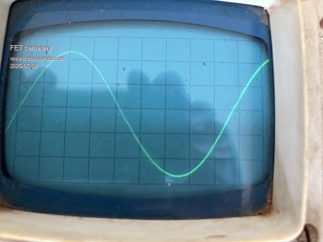 The original scope pic from the bench test, right way up. You have to squint to see it but there's a tiny kink in the waveform after the zero crossing. No stone unturned, no FET unburned. |
||||
| KeepIS Guru Joined: 13/10/2014 Location: AustraliaPosts: 2142 |
Why was a 4.7uf across the 9vac output? or was typo. NANO:Inverter V 8.2ks - Linux AvrDude GUI script V4.1 |
||||
| wiseguy Guru Joined: 21/06/2018 Location: AustraliaPosts: 1286 |
Inverters are a but kinky - the small kink you see is quite normal, on some it is a little more pronounced others a little less. I think yours is normal/fine. KeepIS - can you disconnect the transformer/choke on your test unit and see what the power is at idle and ~54V DC (obviously with 99% FET drive) just as a reference point compared to the 7W found on FC's unit. Taa. (I cant find my bench currently....) Edited 2025-05-09 15:14 by wiseguy If at first you dont succeed, I suggest you avoid sky diving.... Cheers Mike |
||||
| KeepIS Guru Joined: 13/10/2014 Location: AustraliaPosts: 2142 |
 7.8 watts. 7.8 watts.NANO:Inverter V 8.2ks - Linux AvrDude GUI script V4.1 |
||||
| FET cemetery Regular Member Joined: 17/04/2024 Location: AustraliaPosts: 74 |
"Why was a 4.7uf across the 9vac output? " Without a cap across the output the scope trace was noisy with a hint of sinewave. Could be the limitations of my '70s vintage scope. No stone unturned, no FET unburned. |
||||
| KeepIS Guru Joined: 13/10/2014 Location: AustraliaPosts: 2142 |
Perhaps a small RC filter might be better, if it's a small transformer it might be a very low current rating, something like a 5.6k in series with 47nF cap across the output, cro across the 47nf. NANO:Inverter V 8.2ks - Linux AvrDude GUI script V4.1 |
||||
| FET cemetery Regular Member Joined: 17/04/2024 Location: AustraliaPosts: 74 |
"Perhaps a small RC filter might be better". Yep, didn't think that one through, the little transformer is a couple of orders of magnitude smaller than the big toroid! Will try it on the weekend. No stone unturned, no FET unburned. |
||||
| phil99 Guru Joined: 11/02/2018 Location: AustraliaPosts: 3229 |
A kink in the output voltage close to a falling zero crossing implies a kink in the magnetizing current component of the total primary current** close to its positive peak due to it's 90° lag. That suggests the positive magnetizing current peaks are a little closer to saturation than the negative peaks. If the voltage kink is always on the same zero crossing after each start the drive may be the source. If it is sometimes on the other zero crossing and / or a different size after each start it my be just a little remnant flux that will disappear under load. ** The magnetizing current is the difference between the primary and secondary amp-turns vectors. |
||||
| oreo Senior Member Joined: 11/12/2020 Location: CanadaPosts: 133 |
Seems like the electronics are drawing the right current. A shot in the dark. -have you measured your inductors? I know 4 turns with 8 MS225 cores gives you 20uH with 125 permeability cores like KeepIS has, however if say you had 60 permeability cores you would only get 10uH. The cores I have in my build are only 40 permeability, which means I need even more turns. That with the fairly large 4.7uF capacitor on the output of the transformer might result in a higher idle current and noise. A quick test to see if this is an issue, would be to put 3 additional turns of thin gauge wire on one of your cores. If your cores have a permeability of 60, then this would push the inductance of that one core to 30uH, giving you 40 in total. Greg |
||||
| FET cemetery Regular Member Joined: 17/04/2024 Location: AustraliaPosts: 74 |
Oreo, chokes measure 35uH each. This choke, transformer and capacitor combination are in use on my egs002 / powerjack inverter at the moment with no problems other than a bit of a buzz at 4+ kW due to the limitations of what's driving it. Revisited the bench test with a more appropriate capacitor and powering through a 1A fuse rather than the light globe. All at 18V. Scope straight across the output terminals, no transformer: 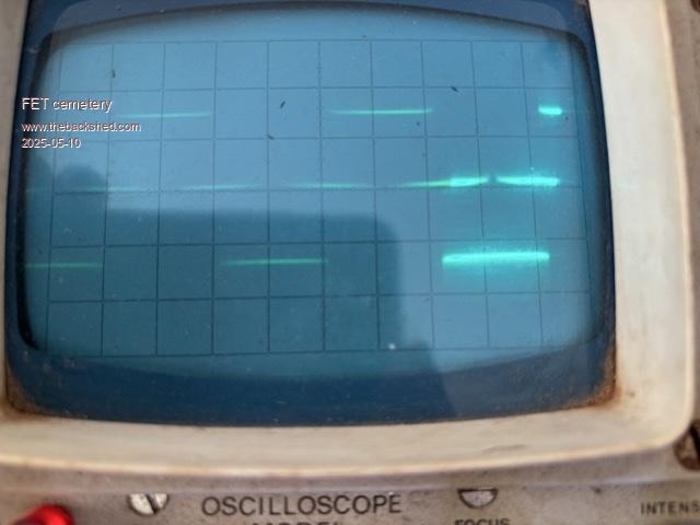 Output driving the 240V primary of a tiny 300mA transformer, scope across the 9V secondary: 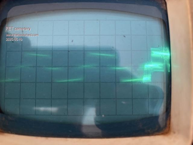 100nF and 2k2 in series across the transformer secondary, scope across the capacitor: 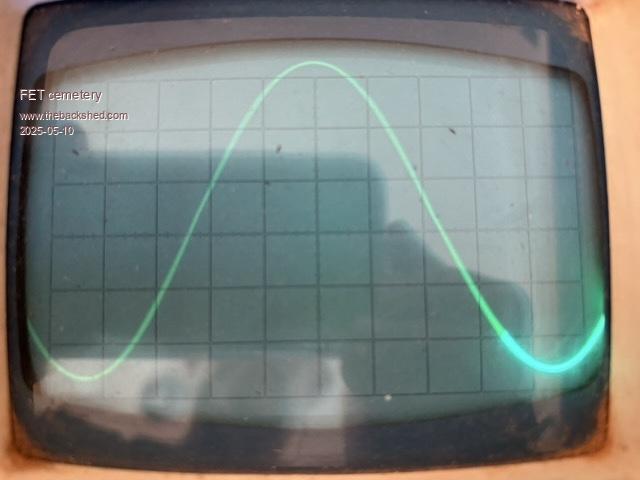 Zooming in on the timescale you can clearly see the pwm: 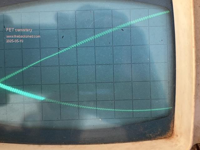 Even more obvious when the resistor is removed: 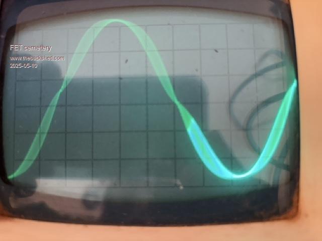 Edited 2025-05-10 17:39 by FET cemetery No stone unturned, no FET unburned. |
||||
| FET cemetery Regular Member Joined: 17/04/2024 Location: AustraliaPosts: 74 |
Interestingly, not even a hint of zero crossing wobble in the third image above. The big transformer was charging the car today and will be running the kiln tomorrow, making hay while the sun shines. Once that's done I might test at 36V with say a 2A fuse instead of the light globe to see if the hum is gone, tempted to just wait for the power supply to arrive though. I really shouldn't be in a hurry, the present setup can put just over 4kW into the car which is pretty much all our surplus power at this time of year on a sunny day, we're optimised for summer airconditioning. Need more solar! Edited 2025-05-10 17:51 by FET cemetery No stone unturned, no FET unburned. |
||||
| KeepIS Guru Joined: 13/10/2014 Location: AustraliaPosts: 2142 |
With low value of caps a 2A fuse and reduced voltage there is almost no chance of damaging the FETS. But I agree, after all the work you put in, it's safer to bring the current limited voltage up slowly, so far everything appears to be good with the globe removed. FYI, the 1A fuse should be fine for 18v to 53V as Idle power should not change much at all. I assumed you were driving the Toriod with the revised setup? So just to clarify the last 3 CRO images, were these taken driving the Toroid and the small isolation transformer across the AC output and feeding the CRO? . Edited 2025-05-11 13:40 by KeepIS NANO:Inverter V 8.2ks - Linux AvrDude GUI script V4.1 |
||||
| FET cemetery Regular Member Joined: 17/04/2024 Location: AustraliaPosts: 74 |
No toroid in these pics just the little transformer. Have to partly dismantle the existing inverter to test with the toroid. Might give it a go at 18V once the powerjack setup has finished running the kiln. Edited 2025-05-11 14:43 by FET cemetery No stone unturned, no FET unburned. |
||||
| KeepIS Guru Joined: 13/10/2014 Location: AustraliaPosts: 2142 |
Thanks, would like to see if it was the unstable supply causing some or most of the problems, if I had the correct globe I could test it myself. NANO:Inverter V 8.2ks - Linux AvrDude GUI script V4.1 |
||||
| FET cemetery Regular Member Joined: 17/04/2024 Location: AustraliaPosts: 74 |
OK, tried it with the toroid and a 1A fuse at 20V (fully charged drill batteries) and the problem / hum is worse. At 40V the fuse blew, but not before I saw 237V output and pwm down to 98%. Something weird is going on. About 700mA at 20V, clearly more than 1A at 40V. The hum at idle is worse than the buzz when it's being driven by the powerjack board at 4.3kW. The fact that it is worse with a more stable supply voltage is consistent with it being worse still with the big 5600uF capacitor I think. Waveform with 20V in, 115Vac out, the zero crossing kink is back: 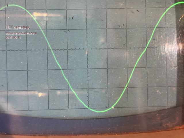 I'm leaning towards the KeepIS gate resistor antenna theory, they're sandwiched between the PCB copper and the Al heatsink with only a couple of mm clearance, but I really don't know. Putting it aside for now until the power supply arrives. No stone unturned, no FET unburned. |
||||
| The Back Shed's forum code is written, and hosted, in Australia. | © JAQ Software 2026 |
