
|
|
Forum Index : Windmills : - NEW ALUMINIUM BLADES -
| Author | Message | ||||
oztules Guru Joined: 26/07/2007 Location: AustraliaPosts: 1686 |
[quote] The Cp does indeed influence the thrust force. If your rotor captures a certain percentage of the wind there has to be a reactionary force behind that. Energy has to be conserved. [/quote] Thank goodness for that, the blade calculator has a problem I think. As i changed the cp from .3 to .6, the thrust remained as before but the power doubled....and I could not fathom this behaviour.... it's not perfect either. The 1000rpm is a realistic outside possibility, particularly if the load is lost for some reason (electrical fault, broken wire, faulty sliprings etc). The loads would then be electrically nill, and the blades would run twice design TSR.... this puts 1000rpm well within reach, but loading would be minimal I suspect, only the drag from the blades.... So centrifugal will be the killer then.... and then the yaw problem. I don't see excessive blade load as the #1 killer but fatigue on poorly supported aluminum will also fight for first place., if supported well, then I don't see it as an issue......but I have my own problems with blade design as will be seen soon. Thanks for straightening that out for me. ............oztules Village idiot...or... just another hack out of his depth |
||||
| Perry Senior Member Joined: 19/11/2009 Location: Posts: 190 |
Hello, Here's my next model. I kept hitting a brick wall with the stresses getting way too high given the initial assumptions. Go figure, I think any 3.2m dia rotor spinning straight into 65 mph winds at 1000 rpm would fail. Let's take a step back and I am going to 'suggest' some initial conditions. A lot of people have made suggestions and comments and I am trying to incorporate them. I am trying to model right when the turbine starts to furl. It is seeing the wind perpendicular to rotor at this point. The thrust forces should be highest here. Once it furls it should be slowing down or in a perfect world holding perfectly steady, right? This model also uses a sched 40 3/4" steel pipe as the internal support rod. No metal rod and thin walled tubing as Oz has suggested. Assumptions; - 1.5m alum extrusion over 1.625m sched 40 steel pipe - Furling speed for the turbine is 15 m/s (33.6 mph) - Rotor dia is 3.2 m - TSR = 5 - Rotor Cp is .30 which has an associated axial induction factor (a) of .019 this means that the rotor is capturing 30% of the power in the wind. Betz limit is 59%. Gen and other losses don't matter at this point. 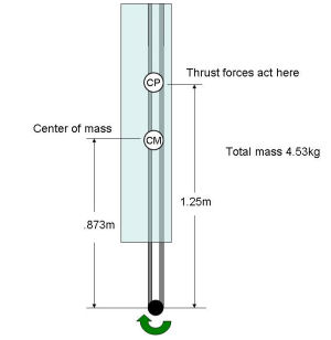
Determine how fast the rotor is spinning at furling point rpm = (TSR x windspeed x 60) / (pi x D) rpm = (5 x 15m/s x 60)/(3.14 x 3.2m) rpm = 448 rpm convert to radians/sec w = (2 x pi x rpm)/60 w = (2 x 3.14 x 448rpm)/60 w = 46.9 rad/sec Calculate the centrifugal forces Fc = M x R x w^2 Fc = (4.53kg) x (.837m) x (46.9rad/sec)^2 Fc = 8331 Newtons = 1873 lbf. Given the cross sectional area of the pipe of .000214 m^2 we can calculate the tensile stresses in the pipe. tensile stress = F / A = (8331 N)/(.000214 m^2) tensile stress = 38 MPa = 5511 psi. Calculate the thrust force As Oz and I were discussing I am going to use a rotor Cp of .30. The rotor will capture 30% of the energy in the wind. This is reflected in the thrust equation by the axial induction factor (a)= .091 The Thrust equation is Ft = 2 x rho x velocity^2 x a(1-a) x Area Ft = (2)(1.223 kg/m^3)(15 m/s)^2(.091)(1-.091)(3.14)(1.6)^2 Ft = 366 Newtons = 82.3 lbf for the rotor Ft = 122 Newtons = 27 lbf for each blade Does this not look a lot more realistic Oz? Given the lower wind speeds and the departure from the betz limit things seem to reflect real life much more. Determine the bending moment this force applies to the blade root I am applying the force at the 3/4 point of the blade towards the tip M = force x distance M = 122N x 1.25m M = 152.5 N-m Calculate the stress in the pipe at the root c for the pipe is the pipe radius. moment of inertia (I) is 1.54x10⁻⁸ stress = M x c / I stress = (152.5N-m)(.0134m)/(1.54x10-8) stress = 132 MPa = 19.1 ksi We can now add the stresses together total stress = centrifugal stress + bending stress total stress = (38 Mpa)(132 MPa) total stress = 170 MPa = 24.7 ksi So where does this leave us? Just buy redefining the question to reflect more realistic circumstances we see that the The stresses from centrifugal and bending moment forces come in at about 24.7 ksi. This is about half the yield strength of mild steel. The highest forces occur right where the pipe connects to the hub. Perry |
||||
| Perry Senior Member Joined: 19/11/2009 Location: Posts: 190 |
To accomadate Oz's suggestion that there is a runaway of 1000 rpm under no load conditions and no real thrust forces we have; Fc = M * R * w^2 Fc = (4.532kg)(.837 m)(104.7 rad/sec)^2 Fc = 41582 Newtons = 9348 lbf stess = F / A stress = (41582N)/(.00214 m^2) stress = 194 MPa = 28.1 ksi So the centrifugal forces become 28.1 ksi. Once again, the pipe will hold if the hub will. Perry |
||||
| oztules Guru Joined: 26/07/2007 Location: AustraliaPosts: 1686 |
Your a wizard Perry. This seems to be more in the realms of what I would anticipate. I think a single supporting member is simple and less likely to fail from poor assembly and stress points. My hubs are made from 14"x 8mm mild steel disks (x2) so my hub would definitely hold these forces in check. The turning center is a 4000lb trailer stub axle... easily rated I should think for this application. It would only see thrust and turning moments from yawing the hub/blade assembly. Do you have a feel for the magnitude of the yaw forces when turning this gyro in the wind? I'm told that they are of similar magnitude to the thrust.... but of an oscillatory nature. I suspect that the reason this was said, is that in this application, the thrust is related to the furling/yawing system... as the thrust increases, we furl out of the way.... or the tail exerts less turning moment on the mill than the mill exerts on the tail via the offset. I find it difficult to see how to equate the spinning mass to what the tube and the hub would see. I guess it depends on the rate of turn involved...controlled by the weight of the tail and the pivot angle used. How do we quantify that.... it all gets a bit murky about now. Well done again. ...........oztules Ps... as oztules runs away, he yells over shoulder.. I think I'd still use solid inch rod though  until I know how the yaw effects the thing. Solid still has 20000 psi (135 Mpa) to go after deformation begins and we bend and hit the tower..... it won't break like bent tube in this case. If the yaw forces appear not to push the tube too near it's limits, I may be swayed though..... or schedule 160 or XXS until I know how the yaw effects the thing. Solid still has 20000 psi (135 Mpa) to go after deformation begins and we bend and hit the tower..... it won't break like bent tube in this case. If the yaw forces appear not to push the tube too near it's limits, I may be swayed though..... or schedule 160 or XXSVillage idiot...or... just another hack out of his depth |
||||
KarlJ Guru Joined: 19/05/2008 Location: AustraliaPosts: 1178 |
Indeed well done Perry. I will cease having sleepless nights on my 2.5m set of blades now even though they have the little tube in them, the big tube goes out 1/3 of the blade instead of the recommended 1/4 and there is no way in hell my little tail could even hope to hold them into the wind long enough for them to hit 1000rpm. Karl Luck favours the well prepared |
||||
| Gizmo Admin Group Joined: 05/06/2004 Location: AustraliaPosts: 5187 |
You could run a wire cable up the middle of the tube. One end attached to the hub and the other attached to a end cap. If the tube to hub mounts fail, or the blade comes loose, the blade wont take off. I know this is a small pathetic contribution to such a informative thread, but I'm tired. 
Glenn The best time to plant a tree was twenty years ago, the second best time is right now. JAQ |
||||
SparWeb Senior Member Joined: 17/04/2008 Location: CanadaPosts: 196 |
I've been missing all the fun! Good of you Perry to fix your work. I haven't had a chance to look at it all - I really don't have any free time these days. I did get a chance to polish up some analytical work I'd done on my own rotor (wood blades) from way back. Added to the clarity and organization and it would be "postable" with a bit more work. One thing I can tackle in a quick posting is the thrust. It is a bit confusing and counter-intuitive when you start calculating things. Oz, you are right to question whether thrust is proportional to Cp at all. In fact it isn't. Thrust on the rotor is proportional to Ct. Nobody around here uses Ct, but it's of vital importance on aircraft and it can be worked out in the wind turbine context. Unfortunately you can't open an aircraft textbook and get a range of Ct for your wind turbine, because the blades are backward! I'll try to do this with words. Picture the wind flowing through the wind turbine rotor and the blades are turning. The blades travel through the air with an angle of attack. Say for the sake of this example it's 5 degrees. For now, ignore the pitch of the blade because at the tip it's nearly zero anyway. The blade is an airfoil, just like a wing. If we were talking about wings, the force would be "lift". Since we're talking about WT blades, we call it thrust. In the case of this wind turbine, the Lift force is directed 5 degrees from the axis of the rotor. That gives you: Thrust = Lift * cos (5 deg) While we're at it: Torque = Lift * sin (5 deg) * radius (I won't discuss torque for now, just focus on the thrust issue.) The case of thrust that I described above is a typical scenario where the rotor is collecting power from the wind and in that case the thrust is proportional to the power. For a while it seems like thrust is related to Cp. But what about the run-away situation, and what about the stalled condition? These make the "Cp" irrelevant, so you can't use it any more. You have to look at the angle of attack in each case, figure out how much lift is present, and then find the component along the rotor axis to find the thrust. The stalled condition is kind of easy. The angle of attack is very high (say 25 degrees) and the blade pitch is counted so the lift force is falling and the angle turns the lift force away from the rotor axis. Thrust (stalled) = Lift (weakened) * cos (25 degrees or more) Stall makes the thrust small. Runaway: The blades are going terribly fast, and just about the only thing keeping them from going faster is the speed of sound. Tips travelling at mach 1 (340 m/sec) will turn a 3m rotor at about 2400 RPM. Whether the wind is blowing hard or not, the faster the rotor turns, the higher its TSR. The angle of attack is small, less than 1 degree. This situation is the deadly one because even with a small angle of attack, the blades have extremely high velocity. The lift force is very high and getting higher. Meanwhile, the angle of attack is pointing the lift force directly in line with the rotor axis. Thrust(runaway) = Lift (increasing) * cos (0 deg) When the electrical load is removed from the generator, the only thing slowing the blades are: - drag - bearing friction - iron losses The amount of power to overcome these is miniscule compared to the power the rotor was supplying to the generator before. Not until the drag becomes large at high rotor tip speeds does the wind power find a new equilibrium with the parasitic power losses. This could happen at tip speeds even higher than 1000 RPM. This all came out a bit quickly and again I have to run. Will check back later to pick up any details I might have dropped in the explanation. --edited a few hours later to correct the angles. I deleted some talk about the pitch of the blade because it makes the explanation more complicated, and it usually isn't 5 degrees at the tip either. Steven T. Fahey |
||||
| SparWeb Senior Member Joined: 17/04/2008 Location: CanadaPosts: 196 |
Okay, I'm getting thrust numbers that agree with Perry's. I'm using a completely different method - I integrated the series of lift forces along the blade given the velocity, angle of attack and wind inflow (with same correction factor "a"). I hope this offers some confidence, seeing the similar result from a very different method. I've also tried a few other scenarios. For example, the same rotor with the same incoming wind could be turning at different RPM's depending on the load the generator imposes: Vw=54kph w=200RPM Cp=0.14 X=1.4 Thrust=49 pounds Vw=54kph w=300RPM Cp=0.23 X=3.4 Thrust=77 pounds Vw=54kph w=400RPM Cp=0.23 X=4.4 Thrust=83 pounds Vw=54kph w=600RPM Cp=0.16 X=6.7 Thrust=84 pounds Or I can set the wind speed higher and see what happens: Vw=100kph w=600RPM Cp=0.24 X=3.6 Thrust=275 pounds Vw=100kph w=1000RPM Cp=0.21 X=6.0 Thrust=298 pounds I can play around and find even worse situations, and the thrust can get up to 400 pounds. Thrust is loosely related to Cp, but after a point it breaks away and it still gets larger even as the Cp gets smaller. Steven T. Fahey |
||||
| oztules Guru Joined: 26/07/2007 Location: AustraliaPosts: 1686 |
Good grief, is there nothing simple about windmills? It does not matter which aspect you chose to examine in detail, electrical,or mechanical... nothing is straight forward, or even reliably calculable.... maybe thats why we persist
Well it appears that thrust is closely related to moment by moment TSR in a given wind speed, which changes second by second....even as SOC changes....and incident wind angles change.... unless you have mppt on a grid inverter..... and even then your furling regime will cause havoc as well. It appears that you can calculate for any given condition, but not be accurate across the range. No wonder they are not idiot proof. Looks like you need a Flux (otherpower) with half a century of experience with these things to get a good feel for what works the best. At least this discussion has given us a feel for what forces can arise from several conditions.... certainly enough to wake me up. With regards to these blades in question, just about any fixing will work up to a point... but stronger is goodderer. It will be up to the individual to get the furling right to protect the system...and thats the devils own job to get right too. (surprise surprise) So step 1....design for early initial furling... particularly if you have an F&P. These blades have a bunch of torque. step 2 build it as strong as you reasonably can step 3 don't push for high power with F&P's/motor conversions, they don't have the ability to stop a mill with late furling...the armature reaction will probably beat you.... furl early or perish. step 4 ... design your axial with lots of stator mounting points ( I use 9 of 1/4" x 2" steel... most use 3) so you can safely stop it in strong winds without stressing the stator. Mine can whoa it up in at least 50 mph winds within 2 seconds without a sound or sign of complaint. (4m blades) Turn it off in a storm and get the furling right.... don't leave it for later. My system auto stops on over voltage conditions lasting for a preset number of minutes consecutively. I don't use dump loads, so as the battery voltage rises over a certain point, they are probably charged anyway.... or the current is getting over the top (50-60A before getting close to charged) This won't work for iron cored machines though. I will have to leave this discussion for now, as I am not able to help move it any further I suspect. I will leave that to the engineers now. Thanks to Perry and Stephen for their invaluable input Luck with it Phill ..........oztules Village idiot...or... just another hack out of his depth |
||||
| SparWeb Senior Member Joined: 17/04/2008 Location: CanadaPosts: 196 |
A good place to leave it. Thank you for the stimulating questions. Steven T. Fahey |
||||
| Perry Senior Member Joined: 19/11/2009 Location: Posts: 190 |
Oz. Don't feel so dejected! As I said before, this isn't impossible to calculate and I have shown you all the formulas and calc's in the last post. You should be proud that your gut instinct is so close to what the math bears out. Sparweb pointed out a lot of good info and a very complex way to look at it. If you'd like you can delve into it on that level but as he said, his numbers tended to match mine which are derived from a simple energy balance equation. As I said in my first post on this thread, everyone was saying the math was too complex to figure out. The reason I got involved was to prove this wrong. Step one is to strip away all the speculation and complexities. Sparweb has added a lot of complexity with that last post that departs from this. In the end, his reasoning is right and the answers come out similar to mine. Steven, The thrust force from a rotor is indeed very dependent on the Cp of the rotor. The thrust force is a reaction to the energy captured from the wind. A high Cp captures more energy and the reactant force is higher. Newton figured it all out for us years ago. Add to that the formula for turbine thrust forces has the Cp right in it as an input. There are cases when my method breaks down, like when furled. But for all the circumstances I can think of, the thrust force will never be higher than what the equation yields. Which is in the spirit of determining the max loads in a simple manner. Also, Steve, your example of the turbine running at 1000 rpm with no load blows up my model. Then again, This condition assumes that something electrical and your furling has broke. At this point your turbine is probably already destroyed anyway. I am confident that my numbers are solid. Perry cringes hoping Flux or Hugh don't post here that he has been wrong all along. Perry |
||||
| SparWeb Senior Member Joined: 17/04/2008 Location: CanadaPosts: 196 |
I hear you, especially for the point of simplicity. I certainly won't bother posting complex math because a) it just looks like boasting and b) there probability of making mistakes is pretty high. Something that trumps both of us is test data. I have read through a bunch of NREL and DOE reports and there is interesting stuff in it. For example, during testing of a Whisper H40 (3meter rotor) they recorded a maximum RPM of 1534 RPM and blade bending moments of 20 N-m (that bending is associated with a yaw rate of 60 degrees per second). There are many gems like this in the test data.
Whisper H40 Report: http://www.osti.gov/energycitations/servlets/purl/828233-Uv9 6Po/native/ Here is an equally useful test on a Bergey Excel-S: http://www.osti.gov/energycitations/servlets/purl/15020498-3 kBCMX/ Also search here: http://www.osti.gov/energycitations/advancedsearch.jsp You can find these and many more test reports if you search for "whisper H40" and "Bergey Excel" (or whatever other WT you want to know about and NREL has tested). It's from the Excel tests that I get a yaw rate of up to 150 degrees per second as a design parameter. When interpreting the meaning of a test and how it relates to a different WT, you want to compare rotor sizes firstly, and then decide which properties are dependent on rotor size and which aren't. In other words, things like RPM are dependent on diameter, while things like yaw rate are probably not. Larger rotors have more inertia, but the wind has more "authority" to swing them around too, evening out the differences. There is thrust data in the reports, too, which is germane to this discussion. Steven T. Fahey |
||||
| Perry Senior Member Joined: 19/11/2009 Location: Posts: 190 |
Dang Steve, Got me all excited but those links don't work. I have dealt a lot with NREL as a result of us selling them a turbine. I will see if I can get ahold of any of their small wind people next week. Perry |
||||
| SparWeb Senior Member Joined: 17/04/2008 Location: CanadaPosts: 196 |
This should "hook up" those links: NREL Begey Excel Test Report 38550 DOE Test of H40 Report (Windward Engineering) Energy Citations Database Steven T. Fahey |
||||
MacGyver Guru Joined: 12/05/2009 Location: United StatesPosts: 1329 |
This thread has gone well beyond where I could ever have imagined it would go. The longer it gets, the more complicated things seem to become. It makes for interesting reading, but for us old hands-on folks, it's just reading for the sake of reading. I have no idea what it's all about. As regards all this, might I make a suggestion? Since the stresses are each a function of differing materials, differing moment arms (fulcrums) and expanding stresses as distance from the hub increases, why not concern ourselves with merely the final third of each blade? By that, I mean use a solid-rod blade shaft (or a tube or carbon fiber or wood or whatever), but attach the "blade" at a point 2/3 the distance from the hub to the wing tip? There's not much power to be lost regarding the inboard 2/3 of the blade, so why complicate things by having a complex curve incorporated close in? I think similar power could be attained from moving the force area of the blade outboard. At that position, a feathering mechanism, which starts steep, then "feathers" to a less-steep pitch would assure starts in low to nominal wind, but also assure higher speed once the whole thing is whirring around like a blur. An analogy might be to view a canoe paddle. Which makes more sense, a big long full-length blade or just a small flat blade near the tip? Using a feather-to-greater-speed mechanism will likely scare some folks, but a furling device can be used to handle over-speeding and yaw stresses would more-easily be handled by a homogeneous solid (or hollow) shaft than a complex extrusion. This started out being about extruded aluminum blades (I think!) and that is light-years ahead of anything I could come up with. Why not use that idea, but augment it into such a manner as to minimize the stresses. Using a "section" acting as a paddle on the end of a round shaft sounds like it might have some merit. You already know I'm all about "simplest is best" and while this may be "too" simple an approach, still it beats the heck out of having to be a graduate engineer, trying to figure out all the 'what-ifs'. Although I know and am grateful for those more clever than I (graduate engineers), the trial and error method in my estimation seems to run a pretty close second here! Hope this helps. If not, I hope it is at least more 'interesting reading'!  Nothing difficult is ever easy! Perhaps better stated in the words of Morgan Freeman, "Where there is no struggle, there is no progress!" Copeville, Texas |
||||
| KarlJ Guru Joined: 19/05/2008 Location: AustraliaPosts: 1178 |
mmmm Yes and no, I agree the airfoil is just along for the ride in the first section of the blade as obviously its angles of attack are wrong as its a constant section of blade no twist, but just as well its there than not there. as for feathering concepts.... counterweights are the only way I can see simply ie when the thing is really going the counterweights fly out and drive it to a feathered position. Like govenors on steam engines I have seen this on a real live (small) windmill, dont know what type it was. But like all complex things....it had failed and was not running at the time I saw it. Luck favours the well prepared |
||||
| HeadsUp Regular Member Joined: 06/12/2009 Location: AustraliaPosts: 43 |
Hello gentlemen ( and ladies if present ) Couple of points of contemplation. re carbon fibre tubes , did anyone do calculations on heavy wall CF tubes and then use a female mating part at the hub joint previous posts have based CF calculations on using 22 ID 25.4 OD which is only 1.7 mm wall there is 25 mm OD CF tube available with up to 4.5 mm wall thickness. excel composites you could then use a K 1045 or 4140 hollow tube hub end eg 25.5 ID and make the OD whatever is required to defeat maximum bending moments as far as fastening is concerned , i like the use of sikaflex aerospace adhesives in combination with shrink couplings , actually in this case i think an expanding bush which fits inside the carbon fibre tube and expands it against the hollow K1045 will have potentials (similar to the link below but obviously much smaller- probably with a single cap screw to lock the assembly) dont knock this method until you look at the clamping forces achievable from cone-lock couplings , though you would probably have to make your own for this application fenlock couplings also , there is an obvious method when fastening the CF tube to the aluminium spar , you cant put glue on the CF tube and slide it inside the spar as most of it will wipe off , so of course what you would do is use a calking gun to put a line of sikaflex along the tube at 12 oclock and 6 oclock , push the tube up inside the spar with the glue lines at 9 oclock and 3 oclock and then rotate it 90 degrees. you will have a pretty complete adhesive coverage , i would then use fasteners through the spar and CF tube towards the outer end so there are no drill holes where fatigue is highest. sikaflex have adhesives which are close to the strength of Aluminium when used in a lap joint from memory 
what does that do to the maths then in regards to mass vs strength ? i would like to find a blade construction where i can use 3 metre blade sections ( 6.4 metre diameter ) next issue..... there must be a few governor designs around ? why not incorporate a mechanical governor that adjusts blade pitch at a maximum RPM rather than furling , or perhaps have both i am not suggesting this approach for the home builder , just looking to address the engineering issues raised. next question , galvanic issues aside , what is the conductivity of carbon fibre in regards to lightning strike ? |
||||
| Perry Senior Member Joined: 19/11/2009 Location: Posts: 190 |
Yes MacGyver it has evolved quite a bit. Sorry if I got a little heavy into the math and I hope this isn't construed as showing off or hijacking this thread. Phill asked for some help and I thought I would chime in. I did try to take the time and spell out all the formulas and include all the units/etc so people could follow along and use the info for their own good. Having said that, Do I believe what I have written will stop people from trying what seems to be right? No. And I guess on some level that is a good thing, right? This is after all a hobby and a big part of that is on the fly creativity. In their book, the Dan's have a great quote; "A week in the lab can save you an hour at the library" Perry |
||||
| KarlJ Guru Joined: 19/05/2008 Location: AustraliaPosts: 1178 |
Conductivity of CF for the most part is negligible. Resin does not conduct electricity at all Thus strike could be an issue. Im also thinking that at these dimensions 3m+ you would be better off with a rougher airfoil that has twist and taper....ie the cheap chainsaw solution, or just buy some big blades suitable for chinese 10KW+ mill. Throwing technology at 3m blade sections is all fine and beaut but you are then working towards the infinite number of blades, at small sections which as 'tules has said before is getting spectacularly complex to build. at 3m+ if you were really into this blade section I'd be looking into pulling a mould off one and making the whole thing from Carbon, not as hard as you would think and you could do some cheating and make a wood or foam core to cut down on material costs as the bit up the guts is doing stuff all anyway. Its a pity as I just threw away about 50KG of 10oz carbon cloth (was offcuts but large none the less) Luck favours the well prepared |
||||
| KarlJ Guru Joined: 19/05/2008 Location: AustraliaPosts: 1178 |
BTW I notice the link to the excel site they also do solid Fibreglass rods, these would be cheap as chips in comparison to the tubes and for our purposes probably just fine (then again probably almost as heavy as steel!) Luck favours the well prepared |
||||
| The Back Shed's forum code is written, and hosted, in Australia. | © JAQ Software 2026 |
