
|
|
Forum Index : Microcontroller and PC projects : Circuit diagram
| Author | Message | ||||
bigmik Guru Joined: 20/06/2011 Location: AustraliaPosts: 2981 |
Hi MB, Lew, All, Now that little beast does indeed look like it would do the job quite well, the input (high level) only needs to be 2.4v I am not sure about the pullups but in anycase the pullups could go to 3v3 instead of 5v and thus be driven from a normal (non 5V tolerant) digital IO pin. I will have to get some myself,, they certainly are cheap enough... I was going to pose a 3v miniature relay but that chip loks a much better idea to me.. Why do you say you need the non-inverting one? If you chose the inverting one you just change the level you set to your uMite pin.. Good pickup.. Regards, Mick Mick's uMite Stuff can be found >>> HERE (Kindly hosted by Dontronics) <<< |
||||
centrex Guru Joined: 13/11/2011 Location: AustraliaPosts: 320 |
If it was me I would try a transistor on the ground pin much like you would if it was a relay. There may be valid objections to do doing that which I am not aware of. Good luck have fun. Cliff |
||||
| bigmik Guru Joined: 20/06/2011 Location: AustraliaPosts: 2981 |
Hi Cliff, As mentioned previously.. It should work reasonably OK BUT you would need to make sure the device is isolated from the GND and there is a possibility that current could flow from 5V through the TX/RX lines into the uMite... That second option I feel is the problem, if it was just used to turn a light on then all would/should be OK but there are other signals involved.. I am NOT certain that there would be current flow through those lines but I suspect there would be and the whole purpose of this is to save power.. I think the device MicroBlocks found looks like a good solution. Regards, Mick Mick's uMite Stuff can be found >>> HERE (Kindly hosted by Dontronics) <<< |
||||
| bigmik Guru Joined: 20/06/2011 Location: AustraliaPosts: 2981 |
Hi Cliff, As mentioned previously.. It should work reasonably OK BUT you would need to make sure the device is isolated from the GND and there is a possibility that current could flow from 5V through the TX/RX lines into the uMite... That second option I feel is the problem, if it was just used to turn a light on then all would/should be OK but there are other signals involved.. I am NOT certain that there would be current flow through those lines but I suspect there would be and the whole purpose of this is to save power.. I think the device MicroBlocks found looks like a good solution. I feel that Lew is starting to hate me as all I ever do is criticise his options... I am trying to be constructive and achieve his desired goals with a minimum of fuss.. I know I lost a lot of hair trying to get the backlight going for my Backpack170 board(s). I learned a lot in that process. Regards, Mick Mick's uMite Stuff can be found >>> HERE (Kindly hosted by Dontronics) <<< |
||||
| MicroBlocks Guru Joined: 12/05/2012 Location: ThailandPosts: 2209 |
You are right. 2.4v is enough. Just went through the datasheet again. That makes it even easier. I did say an 'inverting one'.  
The reason for an inverting one is that when power is applied the uMite pins are in a HIGH-Z state.The pullup will make sure the 'switch' is OFF. Once the program in the uMite takes control you would need the put a LOW on the pin to activate the 'switch'. I think it is because i prefer to control thing by using a sink to ground. It switches 'cleaner' as the ground plane has less impedance and other disturbing influences. You cold use a non inverting one but then you need a pulldown and set the pin high. Something else that is interesting is which level on the input is chosen as the default state as that also influences the amount of current that is used by the chip. Considering that it might be best to use an non-inverting one and use a pulldown resistor. Another reason i personally like this chip is that it is available in a DIP package for easy prototyping AND a DFN for space saving on a PCB. Microblocks. Build with logic. |
||||
| bigmik Guru Joined: 20/06/2011 Location: AustraliaPosts: 2981 |
Hi Jean, All, OOps sorry, too many things spinning in my head at the same time... Yes with the pull down/pullup resistor the value of which will need to be thought about as this will have an inherent current draw in itself. Yes I read all that when I read the data sheet, probably best to have a LOW the normal (most of the time) state and a high the time you wish the unit to be powered. Thinking a bit more on this the pull up/down resistor should only be needed in times of program initialisation so the brief time that would take shouldn't impact anything, the worst it would do is apply power to the GPS (or other) for a short ms or 2 until the program gained control of those pins.. I still think, especially considering Lew wants two such outputs power cycle controlled, that this is the answer but it is Lew's design it is up to him I suppose. Regards, Mick Mick's uMite Stuff can be found >>> HERE (Kindly hosted by Dontronics) <<< |
||||
| MicroBlocks Guru Joined: 12/05/2012 Location: ThailandPosts: 2209 |
I like known states at all time, and default to OFF. This time it is a GPS, but it could also be a valve or something else that could do damage or undesired things when powered even for a slight moment. A resistor is a cheap insurance against that. I will do a little test with them when they arrive and if they work as expected then it is a simple part to add to the toolbox as lots of times you need to switch things on/off. I especially like the 2.4v threshold for a high level. That makes interfacing with 3.3v and 5v parts easy. Microblocks. Build with logic. |
||||
| bigmik Guru Joined: 20/06/2011 Location: AustraliaPosts: 2981 |
Hi Jean, Yes! Understood.. I feel the same.. I think that a pull down probably wont draw any current in either case.. so I am thinking the Non-Inverting TC4427 is the way to go for me. OK with a weak(ish) pull down resistor. I will be getting some DIP chips to play with but I am just going through the SMD package sizes to work out which suit me best going forward with other applications. Regards, Mick Mick's uMite Stuff can be found >>> HERE (Kindly hosted by Dontronics) <<< |
||||
lew247 Guru Joined: 23/12/2015 Location: United KingdomPosts: 1709 |
With the Micromite pin High the transistor will not conduct, the diode is off there is no current drawn the module is not powered When the pin goes low the transistor conducts, the led lights, the HC-12 (or GPS) module gets power and works fine 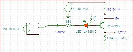
|
||||
| centrex Guru Joined: 13/11/2011 Location: AustraliaPosts: 320 |
Getting back to parasitic power there were a number posts on this subject awhile back when the skinnymite and other mites would stay alive even when the power was disconnected. This happened when a usb to TTL device remained connected, the fix was to insert a schottky diode in the tx line from the USB to the RX on the micro. I know I did this on my skinnymite which fixed the problem. I believe it was TassyJim who came up with the fix. Might allow you to switch the ground! Cliff |
||||
| panky Guru Joined: 02/10/2012 Location: AustraliaPosts: 1130 |
@Mic The way I read the circuit above is that with the MM pin either high or high impedance, the PNP transistor will have it's base held to the emitter voltage by the resistor thus biasing it off (negligible current). When the MM pin goes low, the PNP transistor is biased on and the collector voltage will rise up to near Vcc (less the collector-emitter voltage) providing power for the device. LED should also light. Should work I think. Cheers, Doug. Edit: The 10K base emitter resistor seems a bit high only allowing .5mA to turn on the LED - will depend on LED if this is enough. ... almost all of the Maximites, the MicromMites, the MM Extremes, the ArmMites, the PicoMite and loving it! |
||||
| bigmik Guru Joined: 20/06/2011 Location: AustraliaPosts: 2981 |
Hi Panky, Lew, All, Of course it will be dead easy to test it.. I think I might get some time to experiment in the next couple of days so I intend to test the theory.. I am happy to proven wrong, especially when still at the `paper' stage.. Not having a GPS I am going to use a MuP to try to power control another MuP and I will be able to do some measurements of the ON voltage and OFF voltage and any current draw... Regards and Happy Easter to all. Mick Mick's uMite Stuff can be found >>> HERE (Kindly hosted by Dontronics) <<< |
||||
| HankR Senior Member Joined: 02/01/2015 Location: United StatesPosts: 209 |
Not quite correct. The 3.3 v from the uC is not enough to stop conduction. If the PNP is fed from 3.3 volts as well, 3.3 volts out of the uC WILL stop conduction. Fortunately, there is another way to stop conduction while retaining the 3.3 volt/5 volt split supply voltage setup. That's using not a high out of of the uC, but a floating pin (pin input mode). So uC active low to switch load on, input mode (floating) to switch load off. This has all been hashed out before in previous messages and this is the same basic circuit I proposed to Lew about 3 weeks in PMs, and about 2 weeks ago in public postings. So at this point we're beginning to go around in circles. Correct. So I would think this part of the board is settled. Hank |
||||
| HankR Senior Member Joined: 02/01/2015 Location: United StatesPosts: 209 |
R9 and R10 are unnecessary. It doesn't hurt to have them. In the real old days of germanium transistors they would be needed because of substantial leakage currents. These leakage currents are so small with silicon as to be negligible in most circumstances. I think some of the difficulties evident here for the last couple of weeks in understanding these load switching circuits is due to a tendency to apply digital binary logic level thinking to what is really a linear circuit. So the logic way of thinking about circuit action misapplied to circuits that are not in fact digital can lead to oversimplifications that in turn lead to erroneous conclusions. Hank |
||||
| bigmik Guru Joined: 20/06/2011 Location: AustraliaPosts: 2981 |
Hi Lew, All, My apologies.. I am getting too old and my eyes too bad.. I read the circuit diagram as the uMite pin on the left (going into the Collector of the transistor) and the controlled device (through the LED) on the right.. DOH! 
I can now see the logic behind it... You are using the higher voltage drop across the LED to enable the base to turn the transistor off... Nice... I doubt the LED would light when a LOW is on the umite side, but then it might by the current flowing through the B-E junction, but I dont think that is why you have it in circuit.. Interesting approach.. Regards, Mick Mick's uMite Stuff can be found >>> HERE (Kindly hosted by Dontronics) <<< |
||||
| HankR Senior Member Joined: 02/01/2015 Location: United StatesPosts: 209 |
It's not those BE resistors which power the LEDs. They can be entirely omitted and the LEDs will happily glow with several mA of current! The major LED current flow is through the 680 ohm resistors and the forward biased BE transistor junctions. My preference would be to keep separate the LEDs and their requirements and the base current limiting resistors and their requirements. The arrangement as shown does save two resistors. Hank |
||||
| HankR Senior Member Joined: 02/01/2015 Location: United StatesPosts: 209 |
Correcting the correction I just submitted. I guess the voltage drop across the LED will make it so that the 3.3 out of the uC will be just close enough to 5 volts seeing as how LEDs usually have a voltage drop greater than .6 volts. So using that LED trick, it looks okay after all. Using the uC floating pin mentioned previously for achieving the load-off state means you don't need LEDs or conventional diodes inserted to pad up the uC 3.3 volts. Hank |
||||
| HankR Senior Member Joined: 02/01/2015 Location: United StatesPosts: 209 |
I guess the 3.4 mA LED current in Lew's schematic is being missed by those distracted/fooled by the 10k BE resistors that can be left out entirely. They're totally not needed. |
||||
| HankR Senior Member Joined: 02/01/2015 Location: United StatesPosts: 209 |
Microblocks, Your PM box has reached its limit. Please clear out some room for new PMs. Hank |
||||
| HankR Senior Member Joined: 02/01/2015 Location: United StatesPosts: 209 |
You are so very good at doing PCB designs, please upload to TBS or email to me the complete set of files including Gerbers. I just sent you my direct email, so thanks for making some room in your PM to allow that. This design is fine by me as it stands, even if I have to do a trace cut or two, and twist some transistor leads. Of course even better if you can update to Lew's latest stable design. Hank |
||||
| The Back Shed's forum code is written, and hosted, in Australia. | © JAQ Software 2026 |
