
|
|
Forum Index : Microcontroller and PC projects : Armmite L4 battery miser, first beta
| Author | Message | ||||
TassyJim Guru Joined: 07/08/2011 Location: AustraliaPosts: 6538 |
The Armites have a builtin RTC which is why RTC SETTIME does nothing You would have to roll your own code to talk to a separate RTC My HTU21 is running happily even with the I2C error messages. Jim VK7JH MMedit |
||||
palcal Guru Joined: 12/10/2011 Location: AustraliaPosts: 2039 |
Well that explains that, I will have a bit more of a play around. Flashed the chip again with the code Peter just posted and now I am getting 40c and 10%. Every time I re flash I get different readings and the readings don't change with changed temperature or humidity. So I guess there is a problem with the I2C bus on this L4. E-28 here I come. "It is better to be ignorant and ask a stupid question than to be plain Stupid and not ask at all" |
||||
| TassyJim Guru Joined: 07/08/2011 Location: AustraliaPosts: 6538 |
I blame it on the festivities. Breaking out of a running program with I2C open leaves it open (I think) Doing things properly works as it should. @palcal Try this version. I have added the CRC. It will give values of -999 if the CRC is not correct. Jim VK7JH MMedit |
||||
| matherp Guru Joined: 11/12/2012 Location: United KingdomPosts: 11516 |
Hopefully this time  2019-01-01_182552_ArmmiteL4.zip The Armmite L4 version is the only one with built in I2C display drivers and I was testing for an I2C driver being loaded by looking for the display type being less than or equal to a specific value. Unfortunately I forgot that this test included zero which is the default value for no driver - duh........ |
||||
| palcal Guru Joined: 12/10/2011 Location: AustraliaPosts: 2039 |
Flashed again with the latest and loaded your code JIM, but no go. Thanks for your efforts but I2C on my L4 just won't work. Which pin is for the battery? "It is better to be ignorant and ask a stupid question than to be plain Stupid and not ask at all" |
||||
| matherp Guru Joined: 11/12/2012 Location: United KingdomPosts: 11516 |
I assume you are using a NUCLEO-L432KC? Please check the usual: SDA is the pin labelled A4, SCL is A5 There are no pullups on the Nucleo - these must be supplied externally Check the wires for continuity - so many time things don't work and I find it is the stupid test wires. I haven't got a HTU21 but my test BMP180 works perfectly No separate pin on the 32-pin chip |
||||
| TassyJim Guru Joined: 07/08/2011 Location: AustraliaPosts: 6538 |
The L4 32 pin chip doesn't have a separate pin for battery power. The 48 pin one does (I think) If you are getting -999 it definitely indicates bad checksum. I run my modules without any extra pullups. I don't know what the value of the ones on the module are. I am also running it off 3.3V I can't think of anything else to try. Jim VK7JH MMedit |
||||
| palcal Guru Joined: 12/10/2011 Location: AustraliaPosts: 2039 |
Page one of this thread has a table of pin outs So is it A4 and A5 or D4 and D5 So how is the RTC powered when the board is shut down. I found another Pin Out that says D4 and D5 so I suppose that is it. "It is better to be ignorant and ask a stupid question than to be plain Stupid and not ask at all" |
||||
| TassyJim Guru Joined: 07/08/2011 Location: AustraliaPosts: 6538 |
D4 = data D5 = clock The L4 32 pinner is designed to put in sleep and keep the power to the chip on for the RTC. I do prefer the versions with a dedicated RTC backup pin. Jim VK7JH MMedit |
||||
| palcal Guru Joined: 12/10/2011 Location: AustraliaPosts: 2039 |
That is how I have connected. On the card that came with the board it says Green LED blinks, my green LED does not blink. I tried removing the jumper from D3 to GND made no difference. "It is better to be ignorant and ask a stupid question than to be plain Stupid and not ask at all" |
||||
| TassyJim Guru Joined: 07/08/2011 Location: AustraliaPosts: 6538 |
I assume you are talking about the NUCLEO board. The jumper and flashing light is only with the initial firmware. Not reliant once MMBasic is loaded. Jim VK7JH MMedit |
||||
| matherp Guru Joined: 11/12/2012 Location: United KingdomPosts: 11516 |
That is with the originally loaded demo firmware. D13 is just a standard I/O pin when the Armmite firmware is loaded. Sorry typo, D4=SDA, D5=SCL |
||||
lew247 Guru Joined: 23/12/2015 Location: United KingdomPosts: 1709 |
Is there a PDF for this chip yet? I've got a use for it where it would be ideal as it's such low power and I would only need a couple of pins so there isn't much point in buying a full development board just for it. Other than power I'd only need SPI and 5 other pins |
||||
OA47 Guru Joined: 11/04/2012 Location: AustraliaPosts: 1050 |
Should I be able to save embedded fonts into the library area? 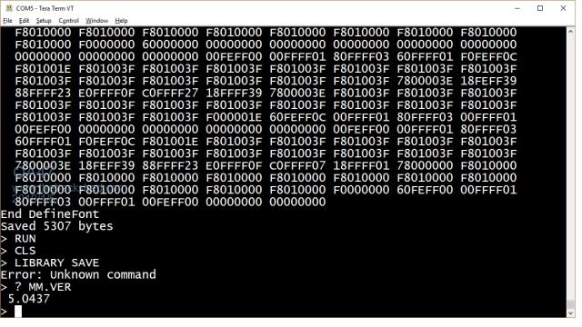 Not sure which commands are supported by the L4. OA47 |
||||
| palcal Guru Joined: 12/10/2011 Location: AustraliaPosts: 2039 |
FRom Page one: "It is better to be ignorant and ask a stupid question than to be plain Stupid and not ask at all" |
||||
| OA47 Guru Joined: 11/04/2012 Location: AustraliaPosts: 1050 |
Thanks Palcal, I did read through that description this morning but missed the "LIBRARY command" bit at the end. I was a little bit confused when Peter posted his 7 segment clock code for the e-Paper display in an earlier post and used font 8 without it in his program code. OA47 |
||||
| lizby Guru Joined: 17/05/2016 Location: United StatesPosts: 3784 |
I've looked through this and other Armmite L4 threads, and while I may well have missed it, I didn't note anything which correlated the mmbasic pins to the text in the first post to the NUCLEO-L432KC (other than by comparing the D# and A# designations). This is my first pass at producing an image: 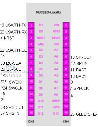 I have a number of questions. Which are console RX & TX? What is A7? What are pin 23 SWDIO and pin 24 SWCLK? Are they rightly assigned to D7 & D8? Are there errors or assigned usage for other pins? Are there count pins? PicoMite, Armmite F4, SensorKits, MMBasic Hardware, Games, etc. on FOTS |
||||
| matherp Guru Joined: 11/12/2012 Location: United KingdomPosts: 11516 |
PA2 is console TX (broken out as A7) PA15 is console RX (not broken out on Nucleo) No, these pins are not broken out on the Nucleo D7 and D8 are the 32KHz xtal pins so not usable The Nucleo manual is the source for the pin allocation of D0 to 12 and A0 to 7 All MMBasic special purpose pins by chip size are given below: The syntax : INT1PIN (HAS_32PINS ? 6 : (HAS_48PINS ? 10 : 14)) //PA0 means INT1PIN is on pin 6 for 32-pin, pin 10 for 48 pin and pin 14 for 64 pin and uses PA0 in all cases. INT pins are the COUNT pins INT1PIN (HAS_32PINS ? 6 : (HAS_48PINS ? 10 : 14)) //PA0 INT2PIN (HAS_32PINS ? 22 : (HAS_48PINS ? 33 : 45)) //PA12 INT3PIN (HAS_32PINS ? 15 : (HAS_48PINS ? 19 : 27)) //PB1 IRPIN (HAS_32PINS ? 6 : (HAS_48PINS ? 10 : 14)) //PA0 //COUNT5 (HAS_32PINS ? 11 : 15) //PA5 // I2C pin numbers P_I2C_SCL (HAS_32PINS ? 29 : (HAS_48PINS ? 42 : 58)) //PB6 P_I2C_SDA (HAS_32PINS ? 30 : (HAS_48PINS ? 43 : 59)) //PB7 // Console pin numbers CONSOLE_RX_PIN (HAS_32PINS ? 25 : (HAS_48PINS ? 13 : 17)) //PA15/PA3/PA3 USART2 CONSOLE_TX_PIN (HAS_32PINS ? 8 : (HAS_48PINS ? 12 : 16)) //PA2 // COMx: port pin numbers COM1_TX_PIN (HAS_32PINS ? 19 : (HAS_48PINS ? 30 : 42)) //PA9 USART1 COM1_RX_PIN (HAS_32PINS ? 20 : (HAS_48PINS ? 31 : 43)) //PA10 COM1_EN_PIN (HAS_32PINS ? 22 : (HAS_48PINS ? 33 : 45)) //PA12 COM2_TX_PIN (HAS_32PINS ? 0 : (HAS_48PINS ? 21 : 29)) //PB10 USART3 COM2_RX_PIN (HAS_32PINS ? 0 : (HAS_48PINS ? 22 : 30)) //PB11 // SPI pin numbers SPI_CLK_PIN (HAS_32PINS ? 7 : (HAS_48PINS ? 11 : 15)) //PA1 SPI_INP_PIN (HAS_32PINS ? 12 : (HAS_48PINS ? 16 : 22)) //PA6 SPI_OUT_PIN (HAS_32PINS ? 13 : (HAS_48PINS ? 17 : 23)) //PA7 SPI2_CLK_PIN (HAS_32PINS ? 26 : (HAS_48PINS ? 39 : 55)) //PB3 SPI2_INP_PIN (HAS_32PINS ? 27 : (HAS_48PINS ? 40 : 56)) //PB4 SPI2_OUT_PIN (HAS_32PINS ? 28 : (HAS_48PINS ? 41 : 57)) //PB5 SPI3_CLK_PIN (HAS_32PINS ? 0 : (HAS_48PINS ? 26 : 34)) //PB13 SPI3_INP_PIN (HAS_32PINS ? 0 : (HAS_48PINS ? 27 : 35)) //PB14 SPI3_OUT_PIN (HAS_32PINS ? 0 : (HAS_48PINS ? 28 : 36)) //PB15 // DAC pin numbers DAC_1_PIN (HAS_32PINS ? 10 : (HAS_48PINS ? 14 : 20)) //PA4 DAC_2_PIN (HAS_32PINS ? 11 : (HAS_48PINS ? 15 : 21)) //PA5 // // PWM pin numbers PWM_CH1_PIN (HAS_32PINS ? 18 : (HAS_48PINS ? 29 : 41)) //PA8 - PWM1A PWM_CH2_PIN (HAS_32PINS ? 21 : (HAS_48PINS ? 32 : 44)) //PA11 - PWM1B PWM_CH3_PIN (HAS_32PINS ? 19 : (HAS_48PINS ? 30 : 42)) //PA9 - PWM1C PWM_CH4_PIN (HAS_32PINS ? 20 : (HAS_48PINS ? 31 : 43)) //PA10 - PWM1D PWM_CH5_PIN (HAS_32PINS ? 9 : (HAS_48PINS ? 45 : 61)) //PA3/PB8/PB8 - PWM2A |
||||
| lizby Guru Joined: 17/05/2016 Location: United StatesPosts: 3784 |
Ok, so I think this is right: 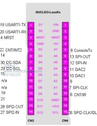 So basically, if you have serial i/o, a display on SPI, a winbond flash file system on SPI2, and I2C, you have 9 i/os left (not counting additional you need for the SPI devices). If you can use an I2C display, you have 3+ more available. PicoMite, Armmite F4, SensorKits, MMBasic Hardware, Games, etc. on FOTS |
||||
| matherp Guru Joined: 11/12/2012 Location: United KingdomPosts: 11516 |
in-built display drivers share SPI2 |
||||
| The Back Shed's forum code is written, and hosted, in Australia. | © JAQ Software 2026 |
