
|
|
Forum Index : Microcontroller and PC projects : PicoMiteHDMIUSB motherboard reference design
| Author | Message | ||||
mclout999 Guru Joined: 05/07/2020 Location: United StatesPosts: 512 |
sorry repost. I wish we could delete them. Edited 2024-11-06 12:47 by mclout999 They call me Shai-Hulud (The maker) |
||||
| phil99 Guru Joined: 11/02/2018 Location: AustraliaPosts: 3331 |
Try pauses between each read, the hardware may need time to read the next value. Test various values to find the minimum. Wii Nunchuck OPEN P = 20 'pause length mS Do Print DEVICE(NUNCHUCK C); Pause P Print DEVICE(NUNCHUCK Z); Pause P Print DEVICE(NUNCHUCK JX); Pause P Print DEVICE(NUNCHUCK JY) Pause P Loop |
||||
| mclout999 Guru Joined: 05/07/2020 Location: United StatesPosts: 512 |
Thanks will do. Next issue. Matherp gave the labels for the inputs for the Nunchuck but not for the classic controller. I wanted to test those next. The CMM3 Manual has a list of what he used there are those, right for the DEVICE(CLASSIC X)? EDIT: even with this code I get the message to enter pin or 0 to restart when you break out of the program. WHAT IS THAT and why is it happening? Edited 2024-11-07 02:35 by mclout999 They call me Shai-Hulud (The maker) |
||||
| Volhout Guru Joined: 05/03/2018 Location: NetherlandsPosts: 6007 |
Hi, The WII classic controller is documented in the 5.08.00 user manual (Geoff's site). Search for "WII" in the document. I think it is page 111. All changes since then are in this writeup summary of all changes Thanks to tha hard work of Mixtel90 Volhout Edited 2024-11-07 02:02 by Volhout PicomiteVGA PETSCII ROBOTS |
||||
| Mixtel90 Guru Joined: 05/10/2019 Location: United KingdomPosts: 8996 |
See manual 5.08.00 and later DEVICE WII OPEN [,interrupt] Opens a WII Classic controller and implements background polling of the device. The Wii Classic must be wired to the pins specified by OPTION SYSTEM I2C which is a prerequisite. Open attempts to talk to the Wii Classic and will return an error if not found. If found the firmware will sample the Wii data in the background at a rate of 50Hz. If an optional user interrupt is specified this will be triggered if any of the buttons changes (both on and off). See the DEVICE function for how to read data from the Wii Classic. Mick Zilog Inside! nascom.info for Nascom & Gemini Preliminary MMBasic docs & my PCB designs |
||||
| matherp Guru Joined: 11/12/2012 Location: United KingdomPosts: 11698 |
bleep, tritonium, JohnS and romba6 please PM me with you addresses and I'll get the boards posted |
||||
| JohnS Guru Joined: 18/11/2011 Location: United KingdomPosts: 4358 |
Thanks - done. John |
||||
| Volhout Guru Joined: 05/03/2018 Location: NetherlandsPosts: 6007 |
Hi Mick, It seems the DEVICE command is not present anymore in 6.0.0 RC 16. It is now something along these lines WII CLASSIC OPEN [,int] WII NUNCHUCK OPEN [,int] Also the DEVICE function has changed. I am eager to see how to read the controllers now. Volhout Edited 2024-11-25 23:30 by Volhout PicomiteVGA PETSCII ROBOTS |
||||
| Mixtel90 Guru Joined: 05/10/2019 Location: United KingdomPosts: 8996 |
That's correct, DEVICE has changed. I can't keep up at the moment. :) It changed in RC12: WII NUNCHUCK OPEN [myint] WII NUNCHUCK CLOSE These commands enable use of a WII NUNCHUCK connected to the SYSTEM I2C pins use the function DEVICE(NUNCHUCK x) to read the nunchuck data where x= AX acceleration in the x axis AY acceleration in the x axis AZ acceleration in the z axis JX joystick x JY joystick y C status of C button Z status of Z button If the optional myint parameter is specified this is a subroutine which is called whenever the C or Z buttons are pressed NB: because the Wii Nunchuck and Wii Classic use the same I2C address only one can be used at a time. If a second device is needed it must be connected to a different I2C channel to the SYSTEM I2C and will need to be configured and read in Basic. Also in this version the following commands can now be used without the DEVICE qualifier WS2812, HUMID, KEYPAD, LCD, WII CLASSIC, WII NUNCHUCK . Edited 2024-11-25 23:49 by Mixtel90 Mick Zilog Inside! nascom.info for Nascom & Gemini Preliminary MMBasic docs & my PCB designs |
||||
| matherp Guru Joined: 11/12/2012 Location: United KingdomPosts: 11698 |
Please don't post non-relevant things on this thread. I'm trying to get people who want boards to respond and messages just get lost when overwhelmed |
||||
| matherp Guru Joined: 11/12/2012 Location: United KingdomPosts: 11698 |
Boards all posted - please PM me when they arrive and I'll let you have paypal details |
||||
| homa Guru Joined: 05/11/2021 Location: GermanyPosts: 651 |
@Peter Important soldering question! 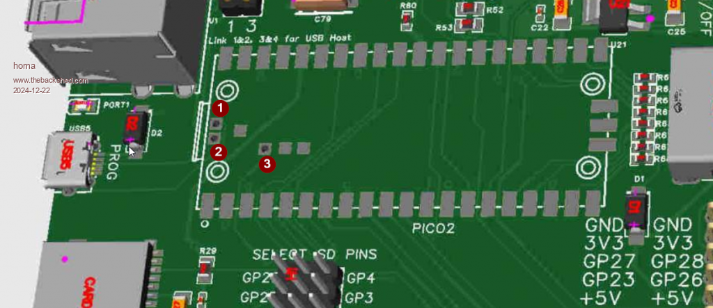 Are there really 4 holes or are there only 3 due to the redesign? My board arrived today and I can only see three! I don't want to make a mistake. Matthias |
||||
| matherp Guru Joined: 11/12/2012 Location: United KingdomPosts: 11698 |
The other hole is under the USB hub - not important - just might help cooling |
||||
| homa Guru Joined: 05/11/2021 Location: GermanyPosts: 651 |
ok, found it. For others who have the same question, here again in dye and colour :-) 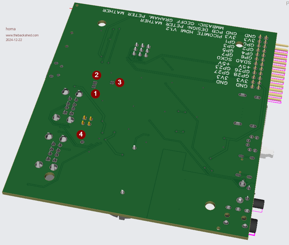 |
||||
| homa Guru Joined: 05/11/2021 Location: GermanyPosts: 651 |
.jpg) My first board is finished :-) The apertures are still missing, but I'll make them on Monday with the small CNC. Thanks to Peter!  Now I'm enjoying my whisky ... and looking forward to it. Matthias |
||||
| twofingers Guru Joined: 02/06/2014 Location: GermanyPosts: 1767 |
@Matthias Thank you for solving the 4 holes puzzle (Peter's riddle.)! The board has just arrived. Thank you very much for that and for the good, careful packaging. Perfect!   And happy New Year!  Regards Michael causality ≠ correlation ≠ coincidence |
||||
| Amnesie Guru Joined: 30/06/2020 Location: GermanyPosts: 763 |
This is a really cool design Peter, will there be an option for socketing the Pico? Yes I am aware of the fact, that they are for connecting the USB programming micro-USB! But if you would allow both (just put holes in the pad) then the user can decide whether he wants to put tiny wires onto the pico for those. Just a suggestion, because you don't really loose anything by doing so, but getting a nice option for excessive pico testing in case it went up in flames  Greetings Daniel |
||||
| matherp Guru Joined: 11/12/2012 Location: United KingdomPosts: 11698 |
Here you go. Same BOM and CPL as before PicoComputer2V1.3.zip 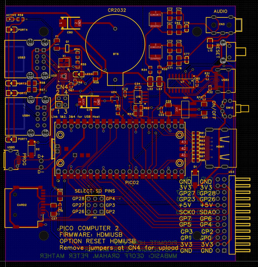 |
||||
| Amnesie Guru Joined: 30/06/2020 Location: GermanyPosts: 763 |
Thank you a lot Peter, I've ordered some with your recent changes! Can't wait to test them Greetings Daniel |
||||
| mclout999 Guru Joined: 05/07/2020 Location: United StatesPosts: 512 |
Is there a possibility of using pogo pins in the Design so that we can socket them? I don't think I have the skills to deSolder The PICO, If it ever fails or if I want to install any of the new boards that have PSRAM. They call me Shai-Hulud (The maker) |
||||
| The Back Shed's forum code is written, and hosted, in Australia. | © JAQ Software 2026 |
