
|
|
Forum Index : Microcontroller and PC projects : Raspberry Pi Monitor doesn't work with PicoMiteHDMI
| Author | Message | ||||
| Volhout Guru Joined: 05/03/2018 Location: NetherlandsPosts: 5934 |
Thanks Lyl, I think you nailed it. Volhout Edited 2025-02-09 00:15 by Volhout PicomiteVGA PETSCII ROBOTS |
||||
| matherp Guru Joined: 11/12/2012 Location: United KingdomPosts: 11522 |
Lyle Very interesting. Questions: Does this change cause any problems with any other monitors that worked previously? Have you tried with 8mA instead of 12? I've had major stability issues when using 12. Sorry to ask, but is your scope properly able to resolve signals at these speeds. What is the analogue bandwith? Are you seeing the full amplitude or is it compromised by the scopes bandwidth? If safe I can easily make the change in my firmware but I would prefer 8mA rather than 12 |
||||
| Volhout Guru Joined: 05/03/2018 Location: NetherlandsPosts: 5934 |
Hi Peter, OPTION HDMI PINS a,b,c,d,drivestrenght ….? With default 8, and options L(4) and H(12) But the speed of the pin is equally important. Harm Edited 2025-02-09 00:32 by Volhout PicomiteVGA PETSCII ROBOTS |
||||
| mozzie Guru Joined: 15/06/2020 Location: AustraliaPosts: 385 |
G'day Peter, Good question, I'll go back and try the monitors that worked previously and report back. Scope is a Tektronix 70Mhz MSO but as you suggest, its not easy getting a good sync on these signals. My cheap 100mhz DSO was hopeless... I did try 8ma but interesting you had trouble with the higher currents, some more experiments required. The slew limit on the pins had a definite effect, might try that at 4ma and see what happens. Regards, Lyle. Edited 2025-02-09 00:39 by mozzie |
||||
| robert.rozee Guru Joined: 31/12/2012 Location: New ZealandPosts: 2529 |
from the RP2350 datasheet, pg 590: • Output drive strength can be set to 2mA, 4mA, 8mA or 12mA. • Output slew rate can be set to slow or fast. https://datasheets.raspberrypi.com/rp2350/rp2350-datasheet.pdf it would be a rather good idea if both parameters could be set on a pin-by-pin basis with extra parameters to SETPIN. perhaps something like: SETPIN pin, cfg [, option][, 2mA | 4mA | 8mA | 12mA][, slow | fast] the same qualifiers could then also be used for pins configured with OPTION - for example: OPTION HDMI PINS 2, 0, 6, 4, 12mA, fast cheers, rob :-) Edited 2025-02-09 00:58 by robert.rozee |
||||
| matherp Guru Joined: 11/12/2012 Location: United KingdomPosts: 11522 |
No chance. Hours of work for minimal utility and high likelihood of user confusion Edited 2025-02-09 01:09 by matherp |
||||
| Mixtel90 Guru Joined: 05/10/2019 Location: United KingdomPosts: 8911 |
Bear in mind the maximum total GPIO current is only 100mA. On a RP2350B that is shared among all the GPIO pins so it's not a lot each. Even with 4mA drive that's 32mA gone out of that 100mA. 12mA drive would leave the chip almost unusable. Mick Zilog Inside! nascom.info for Nascom & Gemini Preliminary MMBasic docs & my PCB designs |
||||
| Volhout Guru Joined: 05/03/2018 Location: NetherlandsPosts: 5934 |
The range of options is limited. HDMI requires minimal 150mV over 50 ohm at the receiver side ( monitor). A 2mA setting will not allow that. And 4 mA will only work when there is no additional losses. But to have slow speed pins when you want to drive a 100Mhz or higher hdmi clock will cause problems. Volhout Edited 2025-02-09 02:53 by Volhout PicomiteVGA PETSCII ROBOTS |
||||
| Amnesie Guru Joined: 30/06/2020 Location: GermanyPosts: 757 |
I think the only solution which makes sense is with an additional circuit, which can act as an buffer... |
||||
| mozzie Guru Joined: 15/06/2020 Location: AustraliaPosts: 385 |
G'day Amnesie, Can you give the program I suggested a try, got the two monitors here working. Also interested to know if anyone else has any luck. Mick / Volhout The 2/4/8/12mA output current setting is a bit of a joke, take a look at the datasheet. Its hopefully not as bad as it looks. The 4 signals are differential and sink current from monitor, so source current is less. We have 220R in series and 50R termination in monitor so 270R total to 3V3 Even with the output set to 12mA the low output voltage is around 0.2v @ 12mA I get 3.1V / 270R = 11.5mA not including cable resistance. So we are sinking 46mA assuming all 4 signals are driven. At the 4mA setting that changes to roughly 42mA, not much different. However this is all DC and not allowing for capacitive loading. Leaves us with 50ish to sink and 90ish to source. Sweet Regards, Lyle. |
||||
| Mixtel90 Guru Joined: 05/10/2019 Location: United KingdomPosts: 8911 |
If the slew rate is the problem then holding the current limit down to 4mA and increasing that would seem to make sense. 150mV into 50R is only 3mA. Setting the limit at 4mA might be marginal in a few cases but it should probably be reasonable over sensible length HDMI leads. I wonder if relying on the resistor to set the current limit might be an idea? 220R or 270R is too low. Mick Zilog Inside! nascom.info for Nascom & Gemini Preliminary MMBasic docs & my PCB designs |
||||
| WhiteWizzard Guru Joined: 05/04/2013 Location: United KingdomPosts: 2991 |
Hi Lyle, I have run your program (saved in Library as a SUB MM.STARTUP) and it WORKS - this is with the RPi monitor at 1280. 1024 also works (it was the only resolution that worked before, and hence continues to work). 640 is now a no-go on this monitor no matter what I do (even the ‘splitter’ is not working at 640). So, from initial tests here with your POKEs program (setting 12mA), it looks like you have resolved the cause of the ‘it may work, but might not’ for HDMI displays. Any further testing that you may require then do post here…… THANKS for looking into this; definitely a step in the right direction. Hopefully something can be set in the firmware by Peter to make HDMI monitors more ‘reliable’ |
||||
| matherp Guru Joined: 11/12/2012 Location: United KingdomPosts: 11522 |
Sounds like it doesn't support 640 x 480 @ 75Hz http://tinyvga.com/vga-timing/640x480@75Hz Edited 2025-02-09 07:41 by matherp |
||||
| WhiteWizzard Guru Joined: 05/04/2013 Location: United KingdomPosts: 2991 |
Referring to the User Manual (from Geoff’s website) I saw the possibility of using: OPTION RESOLUTION 640,252000 This sets the PICO’s output to 640x480 at 60Hz. Happy to say that it worked on RPi monitor so I am pleased to confirm that with Lyle’s POKEs all HDMI resolutions are displayed on all displays that I have here (without the need for any ‘optimiser’ hardware. One PICO has been running for a number of hours now (on a RPi monitor) and there has been absolutely no sign of any jitter or noise - this is a really good sign compared to what has been seen previously. However, I did see some weird & unexpected font size changes so I will try and uncover the exact steps to recreate them so hopefully they can be sorted (one was when I performed a LIBRARY SAVE and the font massively increased at the Command Prompt). Now to add I2S to the setup….. |
||||
| javavi Guru Joined: 01/10/2023 Location: UkrainePosts: 562 |
@Amnesie, Hi Daniel! Can you test this new NES Pico2 firmware for me on your PicoMite HDMI breadboard and "EYOYO" monitor ? picoNES+_PicoMiteHDMI.zip The stability of the NES emulator should improve. And I'm interested in the HDMI+Audio output on this HDMI monitor? Edited 2025-02-09 18:57 by javavi |
||||
| Amnesie Guru Joined: 30/06/2020 Location: GermanyPosts: 757 |
Hi javavi, audio works fine on the Eyoyo monitor! Greetings Daniel |
||||
| mozzie Guru Joined: 15/06/2020 Location: AustraliaPosts: 385 |
G'day, @WhiteWizzard, great to hear it worked for you as well  @Peter, I have tested all except 1 monitor at 12mA and so far so good, but without the scope loading the signals you are correct that 8mA works in all but 1 situation, the BENQ monitor and Fancy cable combo. @All Had time for some further experiments today between other duties... One of those expensive high speed cables I thought might solve some problems is CAUSING some problems  The scope probes also load the signals and skew the results so this is all trial and error. This is the current situation with the two problem monitors: BENQ monitor: Fancy cable 640 stable @ 8mA / fast slew 1024 stable @ 12mA / fast slew (8mA = noise) 1280 stable @ 12mA / fast slew BENQ monitor: Cheap cable 640 stable @ 4mA / slow slew 1024 stable @ 8mA / fast slew (slow = noise) 1280 stable @ 8mA / fast slew ACER monitor: Cheap / Fancy cable via KVM switch (haven't tried direct, buried under mess...) 640 stable @ 4mA / slow slew 1024 stable @ 4mA / fast slew (slow = noise) 1280 stable @ 8ma / fast slew Also tested: WaveShare 7" DVI monitor for PICO (PicoMite plugs onto back with adaptor board for non standard DVI pins) Stable at all resolutions @ 8mA / Fast Generic 10.1" HDMI/VGA/Composite 12V Monitor via short HDMI lead Stable at all resolutions @ 8mA / Fast The fast slew rate option reduces ringing in the cable/monitor combo but its hard to get a good capture on the scope. Increasing the output current looks to do the same. Disabling the Input functions / pull down on these pins also helps in marginal situations. I have one more monitor to test at work, hopefully others can try further combinations to determine if this is a viable fix. Regards, Lyle. |
||||
| matherp Guru Joined: 11/12/2012 Location: United KingdomPosts: 11522 |
My understanding of HDMI/DVI signalling is that the signal pairs should be terminated with 50 ohms BETWEEN THEM AND NOT TO GND - important distinction. This means that with one of the pair set high and the other set low there is an effective resistance of 220 + 220 + 50 = 490 ohms between them. So given a 3.3V drive then the maximum current that can flow is just less than 7mA with one of the pair sourcing it and the other sinking it. The quality of the signal will obviously depend critically on how much capacitance there is in the circuit - hence the impact of the scope probe. In general I've found that setting the slew rate to high increases ringing in most cases. However, it may be in the case of HDMI/DVI it improves things. I have set the slew rate high and the drive to 8mA in b10 (&H21 to the pad control) and am happy to leave it there if we don't get any reports of issues caused. I won't set it to 12mA because, as I stated previously, I have seen this causing instability in processing - CPU crashes. |
||||
| Exile Newbie Joined: 27/05/2023 Location: United KingdomPosts: 28 |
For what it is worth, this is the code that configured the pins in the original PicoDVI code that Luke Wren wrote for the RP2040 and then extended for the RP2350. It is not using HSTX. I wonder if the comments may still be useful? static void dvi_configure_pad(uint gpio, bool invert) { // 2 mA drive, enable slew rate limiting (this seems fine even at 720p30, and // the 3V3 LDO doesn't get warm like when turning all the GPIOs up to 11). // Also disable digital receiver. hw_write_masked( &padsbank0_hw->io[gpio], (0 << PADS_BANK0_GPIO0_DRIVE_LSB), PADS_BANK0_GPIO0_DRIVE_BITS | PADS_BANK0_GPIO0_SLEWFAST_BITS | PADS_BANK0_GPIO0_IE_BITS ); gpio_set_outover(gpio, invert ? GPIO_OVERRIDE_INVERT : GPIO_OVERRIDE_NORMAL); } |
||||
| Volhout Guru Joined: 05/03/2018 Location: NetherlandsPosts: 5934 |
DVI and HDMI physical layer are identical. See these picture from Agilent (who make the testers for HDMI compliance). The differential termination is 100 ohm (each line has its own 50 ohm to a common 3V3 in the TV/Monitor). 50+50=100. 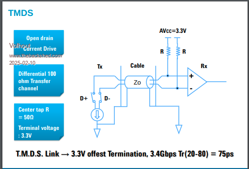 We drive 1 pin low, the other high. For low pin the current is set by the series resistor, and the 50 ohm, and the pico output resistance that differs per drive strength setting. The high pin drives virtually no current (between pico 3.3V and 3V3 termination). 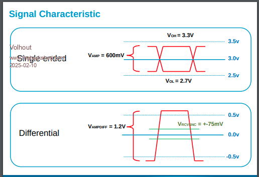 Regards, Volhout P.S. about the slew rate: for 1280 (100MHz+) you will need fast slew rate. It is very well possible that at 640 slow slew rate is acceptable. Note that the HDMI spec talks about rise times of far below 1ns (1ns is a 350MHz bandwidth). But this includes far higher resolutions as well (4k). Edited 2025-02-10 01:47 by Volhout PicomiteVGA PETSCII ROBOTS |
||||
| The Back Shed's forum code is written, and hosted, in Australia. | © JAQ Software 2026 |
