
|
|
Forum Index : Microcontroller and PC projects : Proto Board for the uMite 28
| Author | Message | ||||
bigmik Guru Joined: 20/06/2011 Location: AustraliaPosts: 2981 |
Gday Zonker, You could adapt the Test-A-Mite, which I designed and is now in clearance on Dontronics.com T-A-M It does basic tests for Analog, Digital In&Out and count/freq/period measurements. It wont test the RS485. I wrote the program a couple years ago but it would be fairly easy to rip out the unwanted stuff and modify to uMite pinouts.. it would need an adapter cable to work with your Pinout.. All info and manual is available HERE Whilst that is one option it really might be more practical to just hook 2 uMites together with a suitable cable and run different programs on eack uMite so that one will test the other. Regards, Mick Mick's uMite Stuff can be found >>> HERE (Kindly hosted by Dontronics) <<< |
||||
| WhiteWizzard Guru Joined: 05/04/2013 Location: United KingdomPosts: 2991 |
Hi Zonker, Hope Lou and yourself are getting on good with these nice little modules. 
With regards to testing an assembled board I would consider there to be three things to test: 1> PIC I/O pins connectivity to your MicroMite connector 2> RS485 3> Voltage outputs (5v & 3v3) I would simply test the above as follows: 1> Use a IDC ribbon test lead plugged into your MicroMite connector; the other end expanded out onto a breadboard. Connect 19 LEDs to relevant I/O pins - anode of each led to I/O and all cathodes connected together. Use ONE limiting resistor to ground. Then simple program loop: setpin(x),dout pin(x)=1 pause 500 pin(x)=0 Pass valid values of x and each LED will light in turn. Any not lighting up means a break in connectivity (or a program error!!). As bigmik says, you could use a Test-a-Mite too with a simple mod as this has enough LEDs - just becomes a wire-patching exercise. Note: As long as connectivity exists, I would assume that all other pin functionality works. You could spend time testing all functionality but this depends on the volume of modules you need to ship. I don't think I have ever come across a function (i.e. analogue input) not working on a PIC pin where connectivity does exists. The main test should be connectivity; not functionality testing. I know the above could be strongly debated but . . . . 2> Would do as bigmik says - use two of your boards connected to each other and write a couple of simple comms programs to check RS485 functionality 3> Use your trusty multimeter to measure these two voltages Just out of interest I am building a dedicated test unit for testing my 44-pin MicroMite Modules. This is based around a TFT MaxiMite (provides a nice GUI) and a MicroMite. Will provide 3v3 & 5v readouts as well as 33 x I/O touch testing. This WILL test each pin functionality rather than just connectivity. Unit not finished yet but I will PM you with details once I have finished. Hope the above helps . . . Regards, Phil |
||||
| Zonker Guru Joined: 18/08/2012 Location: United StatesPosts: 772 |
Good evening Phil..! Just got done installing a simple test program in each unit here and just finished testing 10 completed units... All good..! This is the test program being shipped... ' pintest program for uMite 28 pin prototype board Open "com1:9600,de" As #1 Pause 5000 Print "---------- Pintest Program for uMite-28 ----------" Print "" Print "Simple pin tester using an LED and resistor probe." Print "Each pin will be toggled to 1, then back to 0." Print "Use the LED Probe to check each pin on the board." Print "The Rs-485 IC will transmit the pin being tested." Print "A quick check with a scope should verify the pins." Print "" Input "Press any key to start...",a Print "" Print "Init Pins" n=2 ' starting pin number Do int_pin n=n+1 chk_pin Loop Until n=2 Print "" Print "Testing Pins" Do Print n; Print #1,n; If n=26 Then Print "" Pin(n)=1 Pause 20 Pin(n)=0 Pause 20 n=n+1 chk_pin Loop Sub chk_pin If n=7 Then n=9 If n=11 Then n=14 If n=19 Then n=23 If n=27 Then n=2 End Sub Sub int_pin Print n;: Pin(n)=0: SetPin n,dout End Sub I know it is just a simple test, but as you say, just looking for connectivity problems at the moment... No issues so far... All good... Lou is very busy finishing up the last batch of boards at his house. He has been a HUGE help doing all the hardware building for this production run..!! I big tip of the hat to him.!! Not sure what the total hours are for the build, but it has been more than a week of time... So far, I have 10 boards checked and ready for ship next week. So, if the rest check out ok, that should be a total of 20 boards minus 2 for samples leaves 18 for sale... After talking with Lou, we decided to set the price for "full builds" at $35 and board flats at $4... So far, I have an address from BigMik, but nobody else has sent me any address data... I want to get the shipping labels done so, PM me... I will try my best to start getting things ready for shipping as soon as I can... I think shipping cost should be around $10 but cant say for sure yet... More info coming soon... 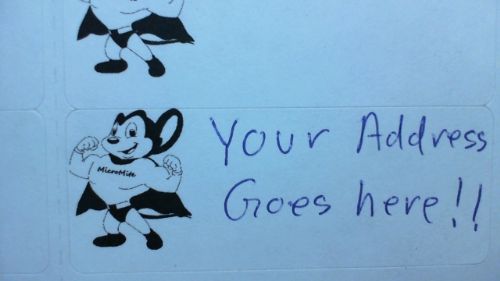
|
||||
| WhiteWizzard Guru Joined: 05/04/2013 Location: United KingdomPosts: 2991 |
Hey - thats the same as my 'Senders Label' !! Disney called round my office the other day and told me that they loved the label  However, I just have to pay them a few million $'s to carry on using it. However, I just have to pay them a few million $'s to carry on using it.
So lets start a fund to raise the necessary money. Please, any donations to either Zonker or myself
|
||||
Grogster Admin Group Joined: 31/12/2012 Location: New ZealandPosts: 9975 |
It really is a great logo, but - yeah - copyright, copyright, copyright. Once you start selling a product using it, you can drop yourself right into a court case. No-one wants that.... @ WW - When Disney called, were they nice enough about it, or all lawyer talk? Smoke makes things work. When the smoke gets out, it stops! |
||||
| WhiteWizzard Guru Joined: 05/04/2013 Location: United KingdomPosts: 2991 |
They were fine. I even managed to sell them a couple of my 44-pin MicroMite modules
They said something about making a film about them. I asked if it could include my soldering technique and that really excited them! |
||||
| Grogster Admin Group Joined: 31/12/2012 Location: New ZealandPosts: 9975 |
Ahhh, that's nice.  MOST people will discontinue doing something, once they realize or are told it is breach of copyright or other - it is so unnecessary to bring out the suits and "Cease and desist" notices and threats of court cases etc, when generally speaking, all most people need, is to be told - nicely - that they need to rethink that aspect.... MOST people will discontinue doing something, once they realize or are told it is breach of copyright or other - it is so unnecessary to bring out the suits and "Cease and desist" notices and threats of court cases etc, when generally speaking, all most people need, is to be told - nicely - that they need to rethink that aspect....
It warms my heart to hear that they did not turn up with cops and lawyers and piles of paperwork threatening to cut off your goulies unless you stop NOW! Smoke makes things work. When the smoke gets out, it stops! |
||||
| Zonker Guru Joined: 18/08/2012 Location: United StatesPosts: 772 |
Hey... I wasn't going to use it "professionally", just thought it was a nice touch to use it between us here at the shed... I kinda like it..! I wish we could use it..! I think it fits the project well... 
|
||||
| Grogster Admin Group Joined: 31/12/2012 Location: New ZealandPosts: 9975 |
Yeah, I know what you mean. I still don't think you are allowed to even do that - trademarks and copyrights - complicated stuff.... 
Smoke makes things work. When the smoke gets out, it stops! |
||||
| WhiteWizzard Guru Joined: 05/04/2013 Location: United KingdomPosts: 2991 |
I think we should all honour Geoff, create a cartoon character of him, and use that instead?
Who want's to ask him . . . . |
||||
| bigmik Guru Joined: 20/06/2011 Location: AustraliaPosts: 2981 |
Lads, Actually Might Mouse is NOT a disney Character, It was created by Terry toons studio for 20th century fox... Unless Disney has bought either of them.. Regards, Mick Mick's uMite Stuff can be found >>> HERE (Kindly hosted by Dontronics) <<< |
||||
| Zonker Guru Joined: 18/08/2012 Location: United StatesPosts: 772 |
Hummm... Never seen his pix... might be a good idea.. not sure... We need something to use as an icon... let's all think on it... |
||||
| bigmik Guru Joined: 20/06/2011 Location: AustraliaPosts: 2981 |
Zonker, Just PM me with what you want $$$ wise from me and a Paypal acct and I will deposit some funds for you. Regards, Mick Mick's uMite Stuff can be found >>> HERE (Kindly hosted by Dontronics) <<< |
||||
| Grogster Admin Group Joined: 31/12/2012 Location: New ZealandPosts: 9975 |
Perhaps the guy who draws those fantastic cartoons for Silicon Chip's SERVICEMAN column, could be persuaded to draw a mascot for the uM!!! Smoke makes things work. When the smoke gets out, it stops! |
||||
| bigmik Guru Joined: 20/06/2011 Location: AustraliaPosts: 2981 |
OK I have it 

Regards, Mick Mick's uMite Stuff can be found >>> HERE (Kindly hosted by Dontronics) <<< |
||||
| Zonker Guru Joined: 18/08/2012 Location: United StatesPosts: 772 |
Nice..!! 
Well, Sent out the 2 sample boards today.. Looks like sending them around the planet will basic-ally cost $10 for the full builds.. As for as flats, haven't sent any yet but will try to get it as cheap as possible... "Combo packs" will probably be a bit more.. Not sure... Will test this tomorrow when I send out BigMik's order... Thanks Mik.. I kinda like it...! |
||||
| Grogster Admin Group Joined: 31/12/2012 Location: New ZealandPosts: 9975 |
@ BigMik - Nice idea! Smoke makes things work. When the smoke gets out, it stops! |
||||
| bigmik Guru Joined: 20/06/2011 Location: AustraliaPosts: 2981 |
Zonker, Best I could do with the little avatar as a sample. WooHoo, Cant wait... I will probably be away on holidays when they arrive but looking forward to seeing them. Mick Mick's uMite Stuff can be found >>> HERE (Kindly hosted by Dontronics) <<< |
||||
| Zonker Guru Joined: 18/08/2012 Location: United StatesPosts: 772 |
Good morning Mik..! Hey, what seemed to help me ALOT is the "fitting jig" I created for the DFN part. Using a square to hold the board on one side and the first part of the jig on the other to keep the board at 90 degree angles. then, the second part to the jig, the very thin piece, is used to bring the reference distance exactly to the wall edge of the DFN part. From there, you just make sure to position the part evenly between the SMD pads and tape it down. I also have a very thin roll of PCB tape to hold the part in place while soldering the pads. If you don't use the jig to hold the part at exactly 90 degrees, the other side would be slightly off-angle and would miss the pad layouts just enough to muff the whole thing up..! I could send you the jig parts and tape along with the order to help you get the DFN's fitted to the PCB... 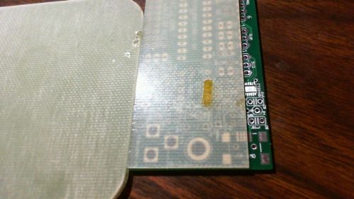
For me, without using the jig, this task would have been impossible..!! The Pix does not show the square on the other side as I left the tool at work... But, you get the idea... |
||||
| bigmik Guru Joined: 20/06/2011 Location: AustraliaPosts: 2981 |
Hi Zonker, I get the idea, I would have the tools here to knock something up... I have to locate a source yet for the FT234XD chips before I get to this stage... The only place I have found so far is MOUSER in HK.. not sure of postage but the chip cost is ok ($2.75, I assume $US) Interesting that NEITHER RS Components nor Element14(Farnell) stock them. Regards, Mick Mick's uMite Stuff can be found >>> HERE (Kindly hosted by Dontronics) <<< |
||||
| The Back Shed's forum code is written, and hosted, in Australia. | © JAQ Software 2026 |
