
|
|
Forum Index : Microcontroller and PC projects : MicroMite 44 Pin TQFP Eval PCB/Module
| Author | Message | ||||
| WhiteWizzard Guru Joined: 05/04/2013 Location: United KingdomPosts: 2991 |
The 44-pin MicroMite Module uses the PIC32MX150F128D. When I have the 50MHz version in my stock I will use it, but sometimes I have to fall back to the 40MHz chip - this is dictated by MicroChips availability as well as current demand from forum members. I do not use the PIC32MX250 on these Modules. [Quote] Interesting that the designation of the chips on the board is unreadable - I guess that's to slow down the cloners? The other chip on the Module is FTDI's popular FT232RL. And the LDO is a STMicroElectronics LF33 (either A or C - both work fine). The chip markings are rubbed off due to the PCB/Flux cleaner I use - Honest! 
Sure the cloners will no doubt become busy when Geoff launches the MicroMite to the world. However, I intend to build up a reputation of providing a range of very high quality MicroMite & MaxiMite products, and customer service with a more personal touch than normal. Maybe it will cost people a little more than the upcoming Chinese copies but I am a strong believer in spending a little more for a much better overall experience. I hope you would all agree with this approach . . . Thanks again paceman for your feedback . . . 
|
||||
| bigfix Senior Member Joined: 20/02/2014 Location: AustriaPosts: 130 |
Sorry for confusion... I do not like to have various versions of a module, as I usually keep some as spare So I wanted the "Full House" version, just to be sure I am aware of the "Other" serial ports - but they are not useable as a programming console port ? I am thinking to install MicroMites on some remote corners in the house and connect their master console port by i.e. Lantronix Xports (Ethernet to serial in a Plug) I got a bunch of those very cheap (normally they cost 70 Euro) This would allow me to connect remotely by a virtual Com port and reprogram the Mite Or I use some plain serial over CAT5 wire for this, easier than extending USB cables USB is perfect to try things quickly in a safe fashion - so it makes lots of sense I proposed a solution to allow both worlds to coexist by connecting a plug/jumper But I understand that this requirement is maybe to special - I can work around this It is still a great little Module ! |
||||
kiiid Guru Joined: 11/05/2013 Location: United KingdomPosts: 671 |
Soon I will be able to offer another clone for the 44 pinner. A bit more oriented towards final inclusion instead of breadboards, but still an option, just for a different niche (not overlapping with WhiteWizzard's one). It integrates a good LDO to provide power to external components, a USB bridge and a uSD slot (not supported as of now, but will be very soon) http://dimitech.com/support.php see Microkite. The firmware will have some extra features (subject to when Geoff will release the original, otherwise it will take longer to make it from scratch) and the chip will be MX170, not MX150. If everything goes as planned, I expect the hardware available by the end of April and hopefully the extended software sometime in May or June. I have already ordered a few initial boards so testing will start soon. The original Geoff's firmware can still be used with the only difference of the port names. http://rittle.org -------------- |
||||
| plasma Guru Joined: 08/04/2012 Location: GermanyPosts: 437 |
Hi , whitewizzard , this is a rocksolid peace of technik , id like to say thank you for this. the soldering dosnt look like pro , it is professinal ! the package , the boards and the full assembled sample are worth every cent . Recommended Product ! Delivery time to german 3-4 days , you are also a fast sender . btw: please dont forget the soldering tipps because yours looks much better as mine ! Gtx and thank you again . |
||||
Grogster Admin Group Joined: 31/12/2012 Location: New ZealandPosts: 9975 |
Yes, I agree with you, plasma. The soldering really is so good, I was fully convinced that he must have had them assembled by a factory, but he assures me and others here on the forums, that he did it himself. WhiteWizzard - you need to start a topic on this, so others can see how you did it  - time permitting, naturally... - time permitting, naturally...
In the boards he sent me, I was still able to read the part numbers on the chips with the aid of a strong LED light at the right angle, and a magnifying monocle. But he's not grinding off the part numbers or anything. Smoke makes things work. When the smoke gets out, it stops! |
||||
| plasma Guru Joined: 08/04/2012 Location: GermanyPosts: 437 |
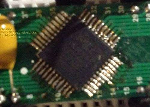
my "soldering" 
haha my board comes with beta 15 
and showed also a personal Message ! whitewizzard : i think it is a good idea to put a link for the usb driver in your description. |
||||
| Grogster Admin Group Joined: 31/12/2012 Location: New ZealandPosts: 9975 |
Should not need driver - Windows should pick it up natively and install it - I did not need to find any driver for my one. Plugged it in, Windows installed the driver without me doing anything, and away I went. What version of Windows are you using? Or maybe now windows at all - Linux or Mac will possibly need drivers, but they are pretty good too. Smoke makes things work. When the smoke gets out, it stops! |
||||
| plasma Guru Joined: 08/04/2012 Location: GermanyPosts: 437 |
haha i use vista because its great ! nah joke its an old lappy so i need the driver installing. |
||||
donmck Guru Joined: 09/06/2011 Location: AustraliaPosts: 1314 |
FTDI Drivers are auto installed by windows 7 and 8. Well not 100%, some people had to fiddle, but that is the way it normally works. XP and backwards will need installing. Check FTDI site for details. Cheers Don... https://www.dontronics.com |
||||
| WhiteWizzard Guru Joined: 05/04/2013 Location: United KingdomPosts: 2991 |
All, Has anybody reading this used iTead Studio's PCB Assembly service (or know anyone that has used it)? If so, what was their quality of work like? Do you have any close-up photos of their SMD capabilities. Thanks for any replies . . .
|
||||
| Grogster Admin Group Joined: 31/12/2012 Location: New ZealandPosts: 9975 |
WW(WhiteWizzard) is really onto something with his soldering method. Here is a photo of a QFP I soldered up using very fine solder and flux-gel: 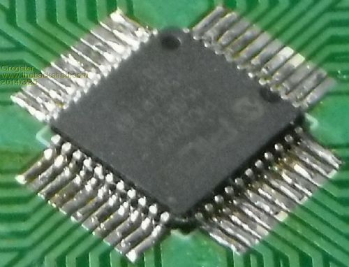
It's OK, but nothing fantastic. It took me about an hour to get right, primarily as I was concentrating very hard on not bridging any pins. Now here is the same board soldered by me, using the WW method: 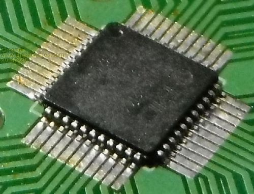
This one took about 5 minutes all up so, it really DOES work!  Smoke makes things work. When the smoke gets out, it stops! |
||||
| robert.rozee Guru Joined: 31/12/2012 Location: New ZealandPosts: 2528 |
just a word of caution - you might want to leave just a little more solder behind, in case a slightly raised pin is left disconnected. i used to always have a fine sewing needle to hand, and would run the point along the rows of pins; a pin that was not soldered down would produce a more 'dull' ping than the rest. rob :-) |
||||
| Grogster Admin Group Joined: 31/12/2012 Location: New ZealandPosts: 9975 |
Clever use of sewing needle! Smoke makes things work. When the smoke gets out, it stops! |
||||
| robert.rozee Guru Joined: 31/12/2012 Location: New ZealandPosts: 2528 |
a trick that arose out of many not-fully-soldered pins being missed! i'd estimate that i've probably soldered over 100 quad packs myself, most using methods similar to those outlined here. plus quite a few FFC connectors and a fair number of CF sockets too, not to mention a thousand or so 0402 resistors and capacitors. oh, the joys of working as an R&D engineer building short prototype runs. rob :-) |
||||
| Frank N. Furter Guru Joined: 28/05/2012 Location: GermanyPosts: 1102 |
Hi Grogster, how did you sold your board with the "WW-method"? With flux and solder wick? Normaly I use a very small soldering iron and solder pin after pin... Frank |
||||
| WhiteWizzard Guru Joined: 05/04/2013 Location: United KingdomPosts: 2991 |
Hi Frank, I can confirm that Grogster did use the WW-method. The two photos he posted (on page 11 of this thread) show what he achieved on a 'practice' piece of board. The top photo was the pin-by-pin method which took him about an hour to complete - all BEFORE he learnt my method. The bottom photo shows his FIRST attempt using my method (after only some guidance via several PMs). This took him around 5 minutes.
Note that NO cleaner has been used in the bottom photo as he didn't have any at hand. If you look closely you can see some brownish markings which would not be there once cleaned. Overall a fantastic and impressive result for his first attempt.
I will be willing to 'train' anyone else (by PM guidance) and hopefully 'convert' a few more of you into SMD soldering experts in less than a day! Regards, Phil |
||||
| PicFan Senior Member Joined: 18/03/2014 Location: AustriaPosts: 133 |
@WhiteWizzard ! I have received 6 pieces Micromite already eight days after the order. What can I say: First class packaging and super fast shipping at low costs!
The PCB, s locks very nice!
Super professional soldering work, how do you do that?
Unpacking and everything worked, with a personal message!
Phil, you're the greatest and the best!
Many, many thanks and best regards also to Geoff. I am happy !  |
||||
| panky Guru Joined: 02/10/2012 Location: AustraliaPosts: 1127 |
Phil, Received my micromite modules yesterday afternoon in good order - well packed and about 8 days to rural Australia. Quality looks excellent but have not had a chance to fire them up yet. Great little product Phil - I look forward to anything else you might come up with. Also thanks to Geoff for the uM software - fantastic. Regards, Doug. ... almost all of the Maximites, the MicromMites, the MM Extremes, the ArmMites, the PicoMite and loving it! |
||||
| WhiteWizzard Guru Joined: 05/04/2013 Location: United KingdomPosts: 2991 |
 I've just finished building my 50th MicroMite Module I've just finished building my 50th MicroMite Module
Along with 13 prototypes that equates to 63. So can I claim the world record for the highest number of 44-pin MicroMites built by one person?? Or is there someone (possibly in China) that can better this? . . . . PS: Also built a few 28pin versions but stopped as soon as Zonker announced his really neat little Proto unit. So does Zonker hold the record for the highest number of 28pin uMites? Please let us know if you think you have built more . . . . |
||||
| Grogster Admin Group Joined: 31/12/2012 Location: New ZealandPosts: 9975 |
Well done you. ...and remember that this is all pre "Official" launch. I expect that both you and Zonker will get busy building modules, once Geoff publishes the chip in the magazine... Smoke makes things work. When the smoke gets out, it stops! |
||||
| The Back Shed's forum code is written, and hosted, in Australia. | © JAQ Software 2026 |
