
|
|
Forum Index : Microcontroller and PC projects : simplest 32MX150 ICSP
| Author | Message | ||||
| vasi Guru Joined: 23/03/2007 Location: RomaniaPosts: 1697 |
In my opinion the entire programmer functionality must be included in MicroMite and switched/transformed into programmer mode by a single MMBasic command. Otherwise I think it won't work. Now, I wonder if Geoff is allowed to do that... Hobbit name: Togo Toadfoot of Frogmorton Elvish name: Mablung Miriel Beyound Arduino Lang |
||||
CircuitGizmos Guru Joined: 08/09/2011 Location: United StatesPosts: 1427 |
Or the middle ground of buying a programmed chip. http://www.circuitgizmos.com/products/cgmicromite1/cgmicromi te1.shtml 
I did something similar with an AVR. (Different interface, though, as it fits perfectly with SPI.) Micromites and Maximites! - Beginning Maximite |
||||
| JohnS Guru Joined: 18/11/2011 Location: United KingdomPosts: 4335 |
There's already an Arduino project but it uses 4-wire (JTAG): arduipic32 There's also a 4-wire RPi & OpenOCD one: RPi_PIC32 John |
||||
| Geoffg Guru Joined: 06/06/2011 Location: AustraliaPosts: 3362 |
It could be done Keith but I am trying to avoid stuffing MMBasic with specialised functions with limited appeal. There are many, many similar functions that individuals would like to see but they would fatally clutter the language if I implemented them all. I think that it would be best to wait until the project is finished and we find out what the real programming time will be. Then we can look at speeding it up if needed. Geoff Geoff Graham - http://geoffg.net |
||||
| Keith W. Senior Member Joined: 09/10/2011 Location: AustraliaPosts: 118 |
Ok, I have begun to communicate with a chip using ICSP from another MicroMite, a WhiteWizzard board with a 32MX150128D 44 pin to the subject 28 pin MX150F128B’s ICSP connector. I started with Mobi’s program but have modified somewhat. JTR0701's posts have also increased my confidence. I place the code here to help others get started. Mobi was trying to erase the chip as an early goal but I have resisted that as the PicKit3 has currently gone back to its owner. I can read the chips ID correctly which is a 32 bit number and I think the Status read is OK. Therefore some things are working. I will try to build on this but have a way to go. I will be grateful if people who are more familiar with MMBasic have a look at my code as I struggle a bit. I have particularly had trouble with using what I had hoped were global variables within subroutines. Finding that they are not visible within the sub? I am trying to minimize processing to increase speed. Using text strings for data seems helpful but may prove cumbersome later. Geoff, thank you for answering my post regarding creating a small Pclock routine. Perhaps the ability to poke a small machine code subroutine into memory from MMBasic and then being able to call it would be a more universal answer. I think this has been written about before, but have forgotten the status. A method of programming a blank chip would be to put in (using ICSP and MMBasic) a small loader that could then communicate via the subject chips hardware serial port from/to the programmer chip to speed the process. This may be faster than bit banging it all on ICSP. Whatever, getting some code in is the first step. 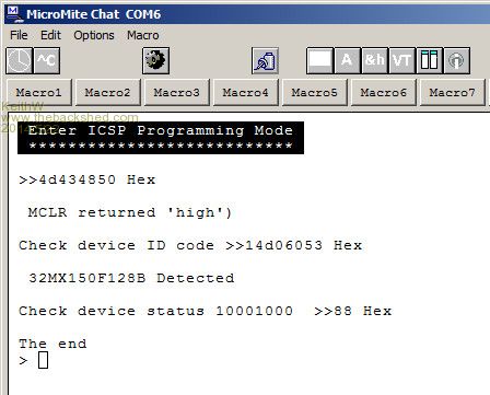
2014-05-22_133526_Keiths_Programmer_MK_2.zip Keith W. |
||||
BobD Guru Joined: 07/12/2011 Location: AustraliaPosts: 935 |
There is a problem with your Setmode sub routine. You are calling it with Gosub Setmode and you have coded the routine SETMODE:
clock 0,1 ' tdi = 0 : tms = 1 clock 0,1 clock 0,1 clock 0,1 clock 0,1 clock 0,0 ' tms = 0 End Sub It needs to be ended with a Return not an End Sub SETMODE:
clock 0,1 ' tdi = 0 : tms = 1 clock 0,1 clock 0,1 clock 0,1 clock 0,1 clock 0,0 ' tms = 0 Return Not sure if that will cause a problem. I seem to recall someone raising that question before. I'll keep looking. |
||||
| JohnS Guru Joined: 18/11/2011 Location: United KingdomPosts: 4335 |
I think it would make more sense (and read better) to make setmode: sub setmode ... end sub John |
||||
| Geoffg Guru Joined: 06/06/2011 Location: AustraliaPosts: 3362 |
That would require the subroutine to be written in MIPS assembler which is not easy. This is because the MIPS processor requires that code be optimised to suit the processor and that is normally done by the C compiler. I do not know of anyone who can write in MIPS assembler. In short, the MIPS processor is a lot more complex than the Z80. Geoff Geoff Graham - http://geoffg.net |
||||
| JohnS Guru Joined: 18/11/2011 Location: United KingdomPosts: 4335 |
Well... it's more or less what Microchip provide (their PE - programming executive) and something similar is part of OpenOCD (and yes it's in MIPS32 ASM). It's something for the future I feel, once there's anything that works - and parts now are! BTW, there's an updated flash programming datasheet PIC32 flashing John |
||||
| JTR0701 Regular Member Joined: 10/07/2013 Location: AustraliaPosts: 71 |
Nice work Keith and congrats on that and also to Mobi and others who helped reach this milestone. Programming the PIC32 via the 2-wire 4-phase method is not straight forward and getting this much done means that there are some of the needed primitives working. IMO what would be interesting at this point is to time how long the code takes to send 481 (4-phase) clocks because that is how many are needed to read a single 32-bit word. This would give as some indication as to the total time required to read the full memory area. From this a decision could be made as to whether this is a workable solution or if other methods need to be employed. In other words are we talking about minutes, hours or what... |
||||
| JohnS Guru Joined: 18/11/2011 Location: United KingdomPosts: 4335 |
I'd love a feel for the time, too! Er, why 481? Seems an odd (ahem) number. I've started looking as an idea at using one of those under $2 USB to DB9 leads and a slightly awkward program on a PC. I know, mad. Bear with me. I think we need 2 outputs (RESET/MCLR & PGECx/CLK) and a third that is both in & out (PGEDx/DATA). Just about doable using as outputs DTR, RTS & TXD (sending no data but rather using its BREAK feature). Input can be one of DCD, DSR, CTS, RI - not sure which is best. Going to need some sort of level shift & open collector stuff or something - help! I only vaguely "do" hardware (I have breadboards, various chips etc, it's design that I struggle with). Is this hopeless (the hardware)? I think I can do the software, though the TXD-using-BREAK is iffy I suspect. John |
||||
| Keith W. Senior Member Joined: 09/10/2011 Location: AustraliaPosts: 118 |
From my oscilloscope on the PGEC wire an 8 bit data transfer which uses about 15 Pclock (4 basic clocks each) per transmissions takes 50 milliseconds. With 30 millisecond minimum between the transmissions. CPU = 40 MHz. Looking at the method used by Kaikkonen the overhead to program is horrendous as it requires about 50 off 32 bit transmissions to load just 32 bits of code. Without reading it back. His method seems to repeatedly load a program in to flash just 32 code bits which is a very slow technique. I may be incorrect but cannot find otherwise yet. Hopefully JTR0701 will tell us that this is not required. The DS6001145(now N) does not use the same method, but without a knowledge of the assembler instructions given it will be a hard grind. Keith W. |
||||
| WhiteWizzard Guru Joined: 05/04/2013 Location: United KingdomPosts: 2991 |
Keith, In your xferdata sub, I believe your tms footer should be '10' (according to datasheet) but you have '00'. i.e. should be 'clock 0,1' two lines before the end of your sub. WW |
||||
| Keith W. Senior Member Joined: 09/10/2011 Location: AustraliaPosts: 118 |
WW, Thank you. I have altered to correct but so far does not act differently. I am happy to find that someone is trying. And more importantly checking. 
Keith W. |
||||
| JTR0701 Regular Member Joined: 10/07/2013 Location: AustraliaPosts: 71 |
"So far does not act differently." Right! You just haven't progressed far enough to see that the whole TAP state machine is now out of kilter. You get away with it (now) because it is virtually the last operation you are doing that is being "misterminated" (is that a word?) Nice catch WW. Potentially this could have saved days of hair pulling troubleshooting later... |
||||
| Keith W. Senior Member Joined: 09/10/2011 Location: AustraliaPosts: 118 |
Well JTR0701, now I have found another error. This time within my Xferdata sub. On the third last clock call of this routine TMS should also be 1. Sub xferdata(st$) y = Len(st$) outdata$ ="" clock 0,1 clock 0,0 clock 0,0 outdata$ = Str$(tdo) + outdata$ 'first bit in For x = y To 2 Step - 1 clock Val(Mid$(st$,x,1)),0 'out outdata$ = Str$(tdo) + outdata$ 'in Next x clock Val(Mid$(st$,1,1)),1 'last bit out ‘******************correct last chr to 1 clock 0,1 clock 0,0 End Sub And fixing these errors has corrected an anomaly that had concerned me. I had found that I must call Setmode again between reading the ID and reading the Status to return the correct status. I had tried swapping the two operations but the second still did not work without a preceding Setmode command.Correct code to be: - Print : Print " Do not recognize chip" EndIf Print : Print "Check device status "; I am happier now. 
Keith W. |
||||
| JTR0701 Regular Member Joined: 10/07/2013 Location: AustraliaPosts: 71 |
Yes, another good catch and another bug squashed. More reason to feel like things are advancing. It is not as if anyone really believes we get stuff like this right the first time. 
The thing about both these two errors is that they are pretty much the same in effect. They both throw out the TAP state machine in the same place (after the data is read) and as you have found, the effect is not immediate but occurs with subsequent operations unless you do something to reset the TAP controller. To be perfectly honest I was looking at your code and wondering how the MCHP_STATUS read after the MTAP_IDCODE read could work but now I understand it was the additional SET_MODE in between that reset the TAP state machine. Ahh! BTW, The nitty-gritty details of how and why it works are not in the microchip programming specification so if you are wondering where I am getting the insight on the TAP state machine it is in the MIPS EJTAG specification MD00047-2B-EJTAG-SPC-03.10.pdf. |
||||
| MOBI Guru Joined: 02/12/2012 Location: AustraliaPosts: 819 |
Hi all, I'm back in internet coverage again and trying to catch up on where we left off. I had been having trouble getting the 'check device status' and 'chip erase' functions to work. The penny dropped the night I arrived in the outback (no internet). In a previous version of my code, I had declared TMS (I think it was) as both a local and a global variable, with the value being declared in the local, but the value in the 'clock' routine coming from the global version, consequently, the value of TMS was incorrect. When I split up the functions and declared a global TMS, I forgot to delete the local TMS. Such a simple thing... Having corrected that bug, the status byte came back as it should and also, the chip performed the erase function ok (the programme I had in the target vanished)as well as the status was still correct. I have to wait till I get home in a few days to read the 'erased' chip with the pickit3 (forgot to take it with me). I think we may even be able to 'download' the Programme Executive that appears in the programming data sheet we have been working from. Translating the 'C' code for PE to MMbasic might cause a bit of brain ache, but I am becoming more confident that we can get there. At least now, I can 'chip' in again. ======= Downloading the PE is described on page 23. There are both the assembly language (MIPS) instructions and the Jtag commands. Just needs a bit of brain power to interpret. If you want to speed up operations a bit, using pulse command instead of pin hi, pin low may also help. David M. |
||||
| JohnS Guru Joined: 18/11/2011 Location: United KingdomPosts: 4335 |
MOBI - good stuff! Post whatever code you're willing, any time. I've got my slightly odd idea part working, though at an early stage (had to order a few CMOS chips). I've got DTR driving MCLR, RTS as CLK (PGECx) and TxD into a counter so I can get a tristate enable and the data out (PGEDx). Can't do data in due to lack of chips (I see MCLR is 5V-tolerant but not PGECx/PGEDx), so will peruse and order some. Can't tell yet whether it'll work at a decent rate (am using 460800 baud for TxD). Turned out the PL2303 USB device outputs (5V) TTL, which I didn't realise, so that was a bonus. I'd thought it was RS232 levels and really would've needed chips then. John |
||||
| Keith W. Senior Member Joined: 09/10/2011 Location: AustraliaPosts: 118 |
Hi Mobi, Welcome back to the fray. In your post you indicate that page 23 of DS60001145 downloads a PE. Well it is a step along the way. Again Microchip documentation leads us astray. The label should perhaps read: - TABLE 11-1: Download a Loader that can download a PE. Table 11-2 is the code required to download a true PE, I think that you can not call this a PE, which communicates at a higher level. Unfortunately "PE loader" can be interpreted in 2 ways here. Likewise Table 14-1 “Verify device opcodes” in my view should be re-labeled: - TABLE 14-1 Reading memory locations. This last caption had confused me and I could not find how to “Read”. The sad consequence is that we must still find or create a PE Loader that we can interact with using MMBasic.A PE is able to put code into Flash but the PE itself I think must reside in RAM.Likely loaders can reside in Flash but Geoff did not have room for this in the MicroMite. Keith W. 
|
||||
| The Back Shed's forum code is written, and hosted, in Australia. | © JAQ Software 2026 |
